The 30-second version
The lead free vs leaded solder decision is settled by regulation first and engineering second.
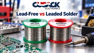
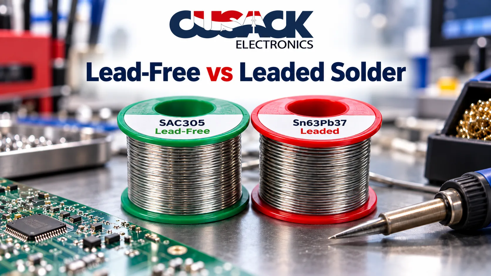
Leaded eutectic Sn63Pb37 melts near 183 degrees Celsius and is easier to work with; lead-free SAC305 melts near 217 and is what RoHS leaves you for almost all equipment sold into the EU.
The exemptions people reach for do not cover ordinary leaded solder, they cover alloys that are 85 percent lead or more, and those entries were rewritten in 2025 with expiry dates inside the next 15 months.
Reliability is the part nobody can give you a straight number on, and the honest reason is that the prediction models are not that good.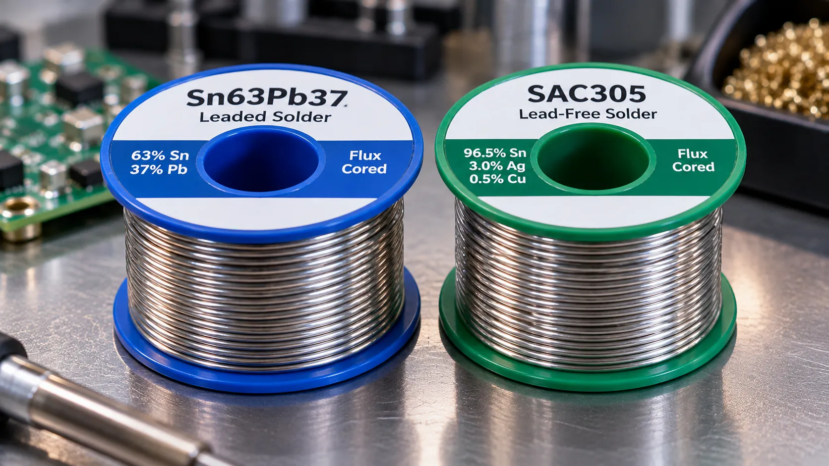
Every comparison of lead free vs leaded solder I read while researching this one had the same shape. A properties table, nine or ten rows, melting point and shear strength and fatigue life, no sources and sometimes no units.
One of them listed fatigue life as “leaded 3, lead-free 1” with nothing attached, then concluded two paragraphs later that the two are equally reliable.
So I am going to do this differently. The regulation is knowable and I will give you the actual directive numbers. The metallurgy is knowable. The reliability comparison is the part where the honest answer is narrower than the tables suggest, and I would rather tell you that than invent a row.
My own default, stated plainly: lead-free on everything, leaded only where a customer has a documented exemption or the product is outside RoHS scope entirely. Not because lead-free is better. Because the compliance position is simpler and I have never regretted a simple compliance position.
What Is the Difference Between Leaded and Lead-Free Solder?
Leaded solder is a tin and lead alloy, usually Sn63Pb37, and lead-free solder replaces the lead with silver and copper, most commonly as SAC305.
Sn63Pb37 is eutectic, which is the property that makes it pleasant to use. A eutectic alloy goes straight from solid to liquid at one temperature with no mushy in-between state, the way pure water goes to ice at a single point rather than thickening gradually.
That single point is about 183 degrees Celsius. No plastic range means no chance of a joint being disturbed while it is half set, which is why a disturbed-joint defect is rarer with leaded wire.
SAC305 is roughly 96.5 percent tin, 3 percent silver and 0.5 percent copper. It is near-eutectic rather than truly eutectic, becoming fully liquid near 217 degrees, and it has a small pasty range on either side of that.
| Property | Sn63Pb37 (leaded) | SAC305 (lead-free) |
|---|---|---|
| Composition | 63% tin, 37% lead | 96.5% tin, 3% silver, 0.5% copper |
| Melting behaviour | Eutectic, single point | Near-eutectic, small pasty range |
| Liquidus | About 183 degrees C | About 217 degrees C |
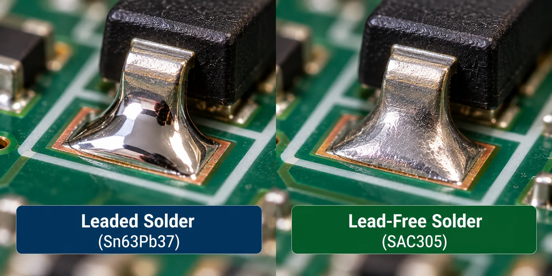
| Joint appearance | Bright and shiny | Duller, slightly grainy |
| Wetting | Spreads readily | Needs more active flux |
| RoHS status in general electronics | Restricted | Compliant |
The appearance row causes more support calls than it should. A dull, slightly grainy SAC305 joint is normal and correct. Inspectors trained on leaded work flag them as cold joints for years afterwards.
How Much Hotter Does Lead-Free Run?
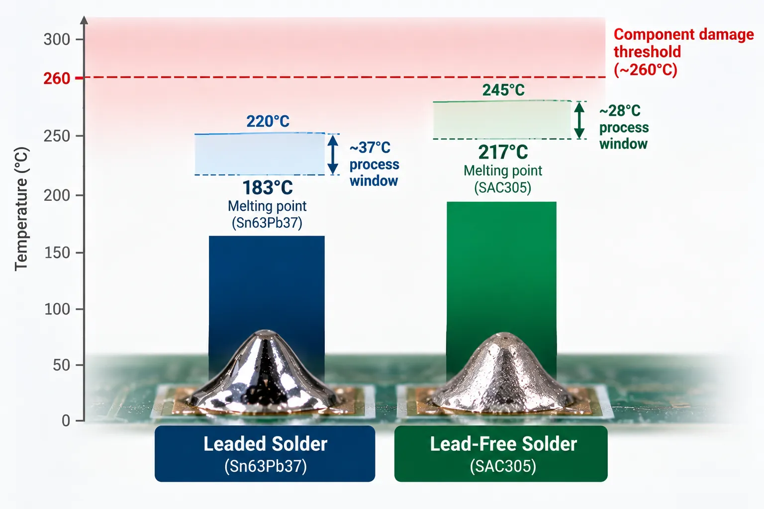
Lead-free runs roughly 34 degrees Celsius hotter at the melting point, and that gap costs you process margin rather than energy.
The problem is not the extra heat by itself. It is that the ceiling did not move with the floor. Component packages carry a maximum classification reflow temperature, and lead-free profiles sit much closer to it, so the usable window between properly molten and thermally damaged is narrower than it was with leaded paste.
Everything downstream of that follows. Hotter ovens, tighter profiling, more attention to delta T across a mixed-mass board, and components that have to be rated for the peak you actually run.
I have set out the stage temperatures, the soak behaviour and how to build a profile for a specific board in my guide to reflow soldering, so I will not repeat the profile table here.
On the through-hole side the same shift applies to pot temperature, which is covered in the wave soldering guide.
Flux is the quiet part of this. SAC305 wets less readily than Sn63Pb37, so lead free solder work generally needs a more active flux to get the same spread, and that pulls the residue and cleaning question along with it.
I have gone through the chemistry families in my guide to the types of soldering flux.
Is Leaded Solder Still Legal?
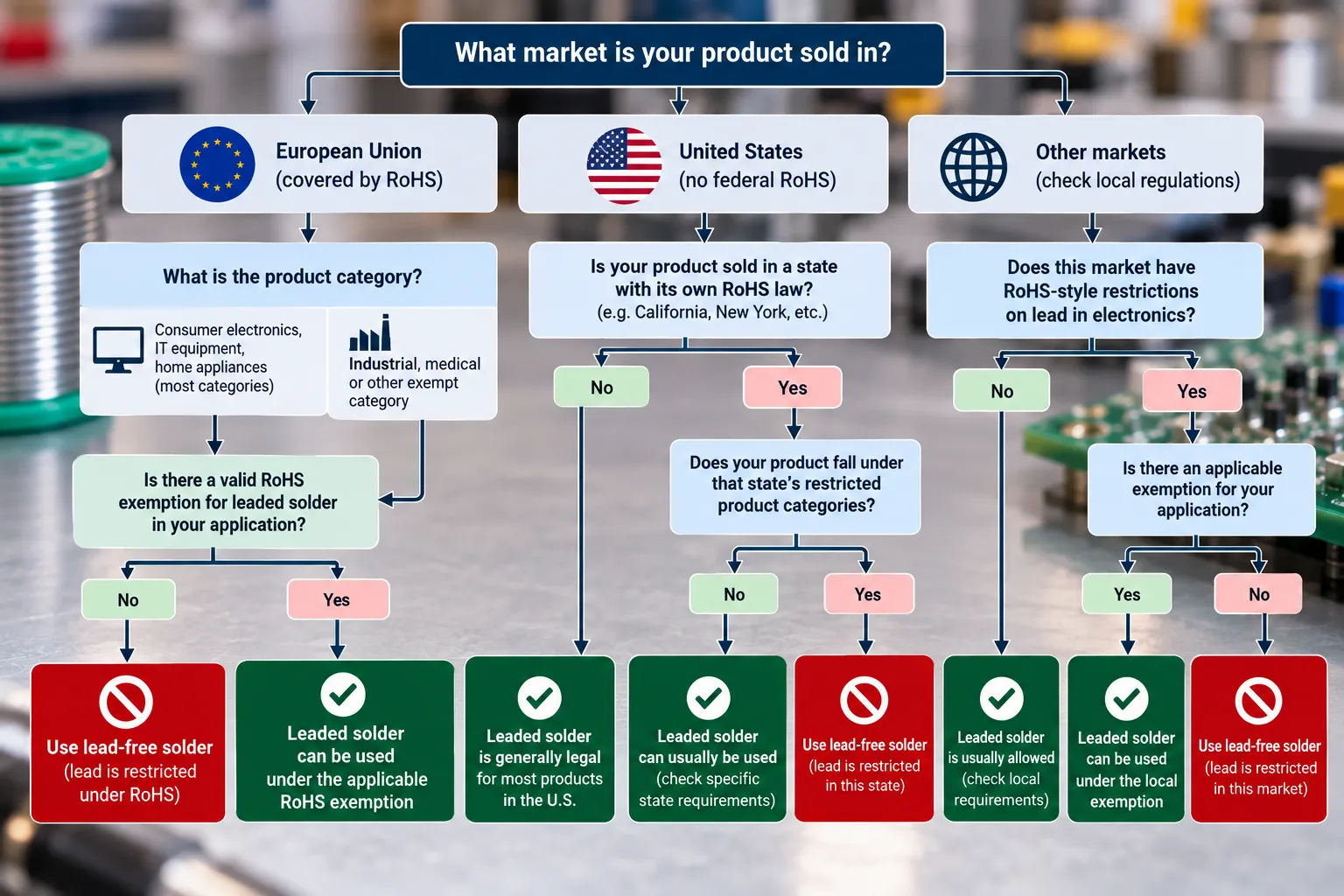
Yes, in several situations, and the common belief that lead in electronics was simply banned in 2006 is wrong in a way that costs people money.
The governing law in Europe is Directive 2011/65/EU, known as RoHS, which entered into force on 21 July 2011 and now restricts ten substances.
Lead is capped at 0.1 percent by weight in any homogeneous material, a limit set in the directive’s Annex II, and ordinary Sn63Pb37 exceeds it by a factor of several hundred.
The Commission maintains the directive and its amendments here.
But RoHS restricts equipment placed on the EU market, and three things sit outside that.
- Out of scope entirely. Military equipment and equipment designed for space are excluded from the directive, which is why aerospace and defence work still runs leaded.
- Covered by an Annex III or Annex IV exemption. These are narrow, application-specific and time-limited, not a general permission.
- Outside the EU, with no equivalent rule. Requirements differ by market, so a product never sold into a restricted market is a different compliance question.
Repair and legacy work also continues. Reworking a leaded assembly with leaded solder is normal practice, and mixing alloys on an existing joint causes its own problems, which I come back to below.
What the Lead Exemptions Actually Cover
The exemption people reach for is Annex III entry 7(a), and it does not mean what most engineers assume. It covers “Lead in high melting temperature type solders”, defined as lead-based alloys containing 85 percent by weight or more lead.
Read that threshold again. Sn63Pb37 is 37 percent lead. It is not a high melting temperature solder and entry 7(a) has never covered it.
What 7(a) actually protects is die attach, hermetic sealing, ceramic BGA solder balls and similar high-temperature joints inside components, where no lead-free substitute survives a later reflow.
And it was rewritten last year. Commission Delegated Directive (EU) 2025/1802, adopted 8 September 2025 and published in the Official Journal on 21 November 2025, replaced entry 7(a) with a base entry plus seven numbered sub-entries.
Member states had to adopt it by 30 June 2026 and apply it from 1 July 2026, so it is live law as of this writing in October 2026.
The expiry dates are the part worth putting in a diary:
| Entry | Scope | Expires |
|---|---|---|
| 7(a) | High melting temperature solders, 85% lead or more | 30 June 2027 |
| 7(a)-I | Semiconductor die attach and internal interconnections above set current, voltage or die-size thresholds | 31 December 2027 |
| 7(a)-II | Integral die attach meeting conductivity thresholds with solidus above 260 degrees C | 31 December 2027 |
| 7(a)-III | First level joints that survive a later reflow during subassembly mounting | 31 December 2027 |
| 7(a)-IV | Second level joints: ceramic BGA solder balls, and plastic overmouldings above 220 degrees C | 31 December 2027 |
| 7(a)-V | Hermetic sealing between ceramic packages or plugs and metal cases | 31 December 2027 |
| 7(a)-VI | Lamp component connections in infrared heating, discharge and oven lamps | 31 December 2027 |
| 7(a)-VII | Audio transducers with peak operating temperature above 200 degrees C | 31 December 2027 |
If your bill of materials depends on any of those, the base entry has under nine months left and the rest follow six months after. Exemptions are routinely renewed, so this is not a cliff edge, but it is a renewal process you should be tracking rather than assuming.
Not one of the seven competing articles I read while researching this cited the directive by number, let alone an exemption number.
Are Tin Whiskers a Real Risk?
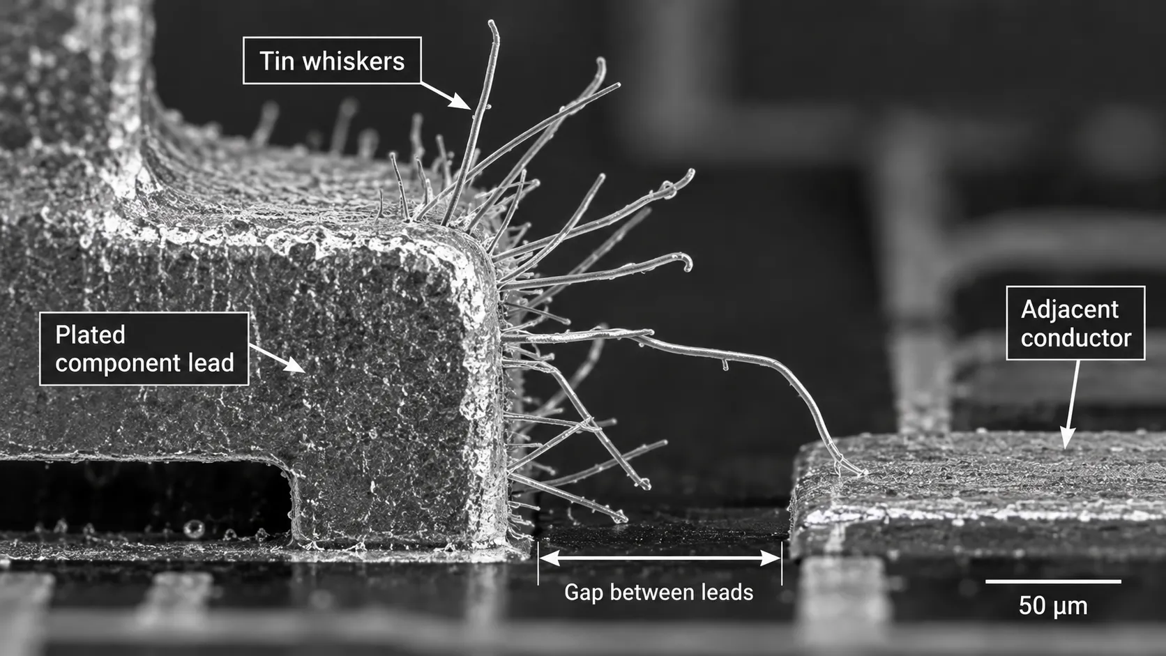
Tin whiskers are thin conductive filaments that grow spontaneously out of tin surfaces and can bridge adjacent conductors, and the documented failures are real, expensive and mostly older than the lead-free transition.
Picture a crystal of metal growing out of a plated surface like a hair, slowly, over months or years, until it touches something it should not. That is the whole mechanism in one image, and the field still does not fully agree on what drives it.
NASA keeps the authoritative public record. On commercial satellites, whiskers growing on pure tin plated relays shorted satellite control processors and caused four total losses: Galaxy VII, Galaxy IV, Solidaridad 1 and Galaxy IIIR, each losing a primary and then a redundant processor.
Four more satellites lost one processor and kept flying. The nuclear power record is similar, including a reactor trip at Dominion Millstone in 2005 traced to whiskers on diode terminals.
NASA’s catalogue is published in full.
Now the part the scare stories leave out, and it matters.
Those failures grew from tin plating on component leads and relay parts, not from the bulk solder joint. Whiskers are a surface finish problem that the move away from tin-lead finishes made worse, which is related to lead-free solder but is not the same thing.
A review by a materials supplier counted roughly twenty referenced failures on NASA’s own list and noted that almost all of them predate July 2006, and that many involved bright tin plate, which has no business in critical electronics regardless of RoHS.
I find that argument mostly convincing and I will say so, with one caveat: it was written by a company that sells lead-free solder, it offers no failure-rate data, and absence of reported failures is weaker evidence than it looks.
The practical position is unchanged either way. Specify matte tin over bright, use a nickel underlayer where it matters, and for space, defence and implantable medical work the answer is still tin-lead, which is exactly why those sectors sit outside RoHS scope.
Which Alloy Gives the More Reliable Joint?
Neither one wins outright, and the specific reason is that the models used to predict solder fatigue life are not precise enough to settle it.
This is where every competing article publishes a confident number and where I am going to publish the uncertainty instead, because that uncertainty is the actual engineering finding.
Michael Osterman at the Center for Advanced Life Cycle Engineering, the University of Maryland reliability group known as CALCE, modelled temperature cycle fatigue across SAC alloys and SnPb using ball grid array test vehicles over five cycling profiles. Three results are worth carrying away.
- SnPb failed more predictably. It had the tightest failure distribution in the set. SAC305, aged and unaged, had some of the widest scatter.
- The ranking depends on severity. SnPb improved relative to the SAC alloys as the damage metric rose, and the alloy curves cross rather than running parallel.
- The models are loose. For SAC305, observed life fell between half and twice the predicted value.
That last figure deserves a moment. A careful academic model, fitted to real test boards, lands within a factor of two in each direction.
One widely used acceleration model, Norris-Landzberg, fitted the SnPb data with an R squared of 0.329, and the author openly questions its usefulness.
The work was presented at SMTA International in 2018 and sits in CALCE’s lead-free research index.
Against that, a blog table asserting “fatigue life: leaded 3, lead-free 1” is not a simplification. It is a precision claim the field cannot support.
One concrete anchor from the same work: a 192 input-output BGA with SAC305 balls and paste, cycled from minus 15 to 125 degrees Celsius with 60 minute dwells, failed at 4,257 cycles, confirmed by sectioning.
Treat that as one data point from one test vehicle, and note the work is from 2018 rather than this year.
The usable conclusion: if your product sees mild thermal cycling, this question is not worth agonising over. If it sees harsh cycling, high vibration or a long qualification life, you need test data on your own assembly, not a comparison table.
One related question gets asked a lot and has no clean answer either. SAC305 forms a stiffer joint than Sn63Pb37, so in theory it should pass more board flex into a ceramic capacitor and crack it sooner.
A NASA Goddard review cites data pointing the other way, with lead-free assemblies cracking less than tin-lead ones. I would not design around either direction, and the bigger lever is the separation process itself, which I have covered in my guide to PCB depaneling.
The Mixed-Alloy Trap
Mixing alloys in one joint is the reliability problem that actually bites, and it is far more common than whiskers.
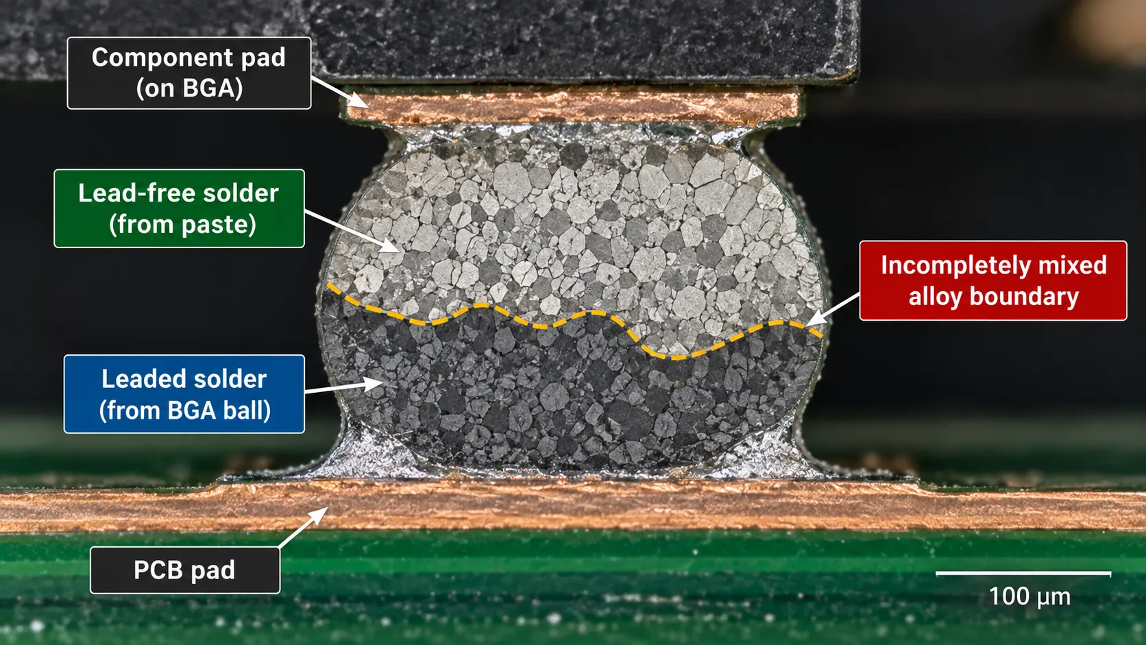
The usual version is a component with Sn63Pb37 balls going through a SAC305 reflow soldering profile, or SAC balls through a leaded one. It shows up most often in BGA assembly, where the ball alloy and the paste alloy are sourced separately.
The result is a joint that is neither alloy, with a composition and melting behaviour nobody characterised.
Inspection will not catch it either, because the joint looks ordinary.
Keep the solder alloy consistent across the whole build: solder paste, component finish and rework wire. If a legacy part forces a mix, treat it as a qualification exercise rather than a substitution, and say so on the build documentation.
What Does Lead-Free Cost?
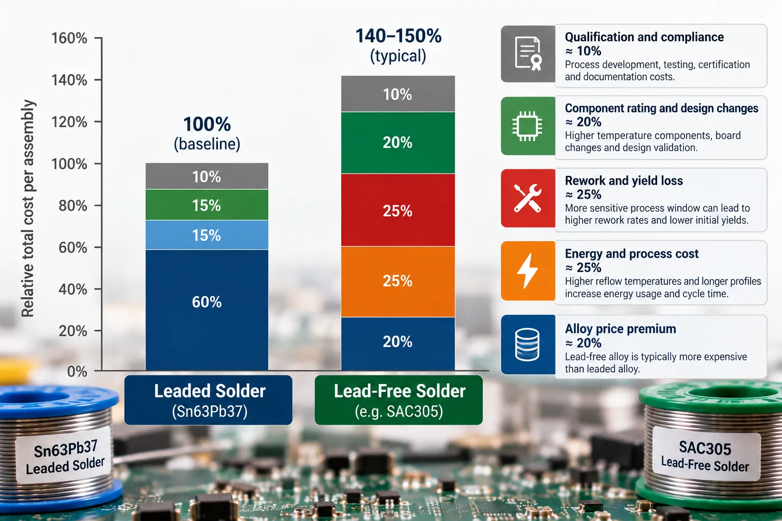
Lead-free costs more per kilogram because of the silver, and more per board because of what the higher temperature does to everything around the joint.
The alloy premium is the smallest part. SAC305 carries 3 percent silver by weight, so its price tracks a commodity that leaded solder is not exposed to, and lower-silver alloys exist specifically to cut that exposure.
The larger costs are indirect:
- Energy and throughput. Hotter ovens draw more power and mixed-mass boards take longer to profile, which touches every stage of the SMT assembly process.
- Component rating. Parts have to tolerate the peak you actually run, which narrows sourcing.
- Rework time. Higher temperatures and poorer wetting make hand rework slower, and slower rework is labour.
- Dross on a wave soldering line. Lead-free pots oxidise more readily, and that is scrapped alloy plus operator time.
- Qualification. If reliability matters, the test programme is the real cost, not the wire.
Where that lands on a finished assembly depends on the board, which I have broken down in my guide to PCB assembly cost.
When Should You Still Specify Leaded Solder?
Specify leaded solder when the product is genuinely outside RoHS scope or inside a documented exemption, and not otherwise.
The honest list is short:
- Space and defence hardware. Excluded from the directive, and the sector’s whisker experience is the reason it stays leaded.
- Class 3 high reliability work under a customer specification that calls for it. The specification is the authority here, not your preference.
- Repair and rework of existing leaded assemblies. Matching the original alloy is the right call.
- Prototyping and bench development, where nothing is being placed on the market and the easier alloy saves time.
- Inside components under a live Annex III exemption, which is a supplier question rather than an assembly one.
Everything else is lead-free, and the workmanship criteria either way come from IPC J-STD-001, currently at revision J issued in 2024, which superseded revision H from 2020.
My caveat, and it is a real one. If you are a small operation building bench prototypes that will never be sold, leaded wire will make your life easier and anyone telling you otherwise is being dogmatic. The moment a product is going to market, that calculus inverts completely.
The Bottom Line
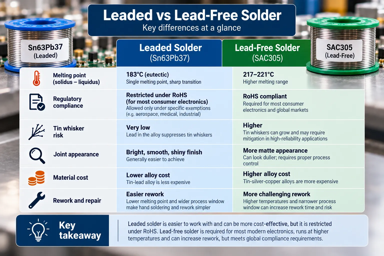
- Sn63Pb37 melts at about 183 degrees Celsius and is eutectic. SAC305 melts near 217 and is not.
- RoHS is Directive 2011/65/EU, lead is capped at 0.1 percent in any homogeneous material, and military and space equipment sit outside it.
- Exemption 7(a) covers alloys that are 85 percent lead or more. It never covered ordinary leaded solder.
- Delegated Directive 2025/1802 split 7(a) into eight entries, applicable since 1 July 2026, expiring across 2027.
- Tin whiskers are a plating problem more than a solder problem, and the documented failures are mostly pre-2006.
- Nobody can tell you which alloy lasts longer on your board. The models land within a factor of two.
- Mixing alloys in one joint is the risk that actually bites.
- Workmanship criteria are the same document either way, IPC J-STD-001, currently revision J.
If you are working out which alloy a new product should be built with, that conversation is cheaper before the first build than after qualification, and the PCB assembly guide covers where this decision sits in the wider process.
Frequently Asked Questions
Can I mix lead-free and leaded solder?
Not deliberately. A joint made from both alloys has a composition and melting point nobody characterised, and the usual failure case is leaded BGA balls run through a lead-free profile or the reverse.
If a legacy component forces it, treat it as a qualification exercise with its own test evidence, and record it on the build documentation rather than letting it pass as a substitution.
What temperature should I set my iron for lead free solder?
Higher than for leaded, but the useful answer is that tip temperature matters less than tip contact and thermal mass. Lead-free needs more heat delivered into the joint, not simply a hotter setting.
Turning the dial up to compensate for a tip that is too small damages pads and burns flux before the joint forms. Match the tip to the thermal mass first.
Is leaded solder actually dangerous to use?
The fume risk at a bench is dominated by flux, not lead, because lead does not vaporise appreciably at soldering temperatures. The real exposure routes are ingestion and dust from handling.
Wash your hands, do not eat at the bench, and use fume extraction for the flux. Follow your own jurisdiction’s occupational health rules rather than a datasheet.
Why do my lead-free joints look dull and grainy?
Because that is what a correct SAC305 joint looks like. The bright mirror finish people associate with a good joint is a property of leaded eutectic alloy, not a quality indicator.
Judging lead-free work by leaded appearance standards produces a steady stream of false defect calls from inspectors who learned on the older alloy.
Does RoHS apply outside the European Union?
RoHS itself restricts equipment placed on the EU market. Several other jurisdictions have adopted broadly similar restrictions, and the details, scope and exemptions differ between them.
Check the specific requirements of every market a product is sold into. Assuming global equivalence because a product is EU compliant is a common and expensive mistake.
Is lead free solder more or less reliable than leaded?
It depends on the loading, and the comparison is less settled than the tables online suggest. CALCE testing found SnPb failed more predictably with tighter scatter, while the relative ranking shifted with cycling severity.
For mild thermal environments the difference rarely drives a decision. For harsh cycling or long qualification lives, test your own assembly.
What is SAC305 and why that alloy specifically?
SAC305 is 96.5 percent tin, 3 percent silver and 0.5 percent copper, and it became the default because it balanced a workable melting point against joint performance when the industry needed a replacement quickly.
It is not uniquely good. Lower-silver alloys trade some fatigue life for cost, and alternatives exist for specific thermal profiles.