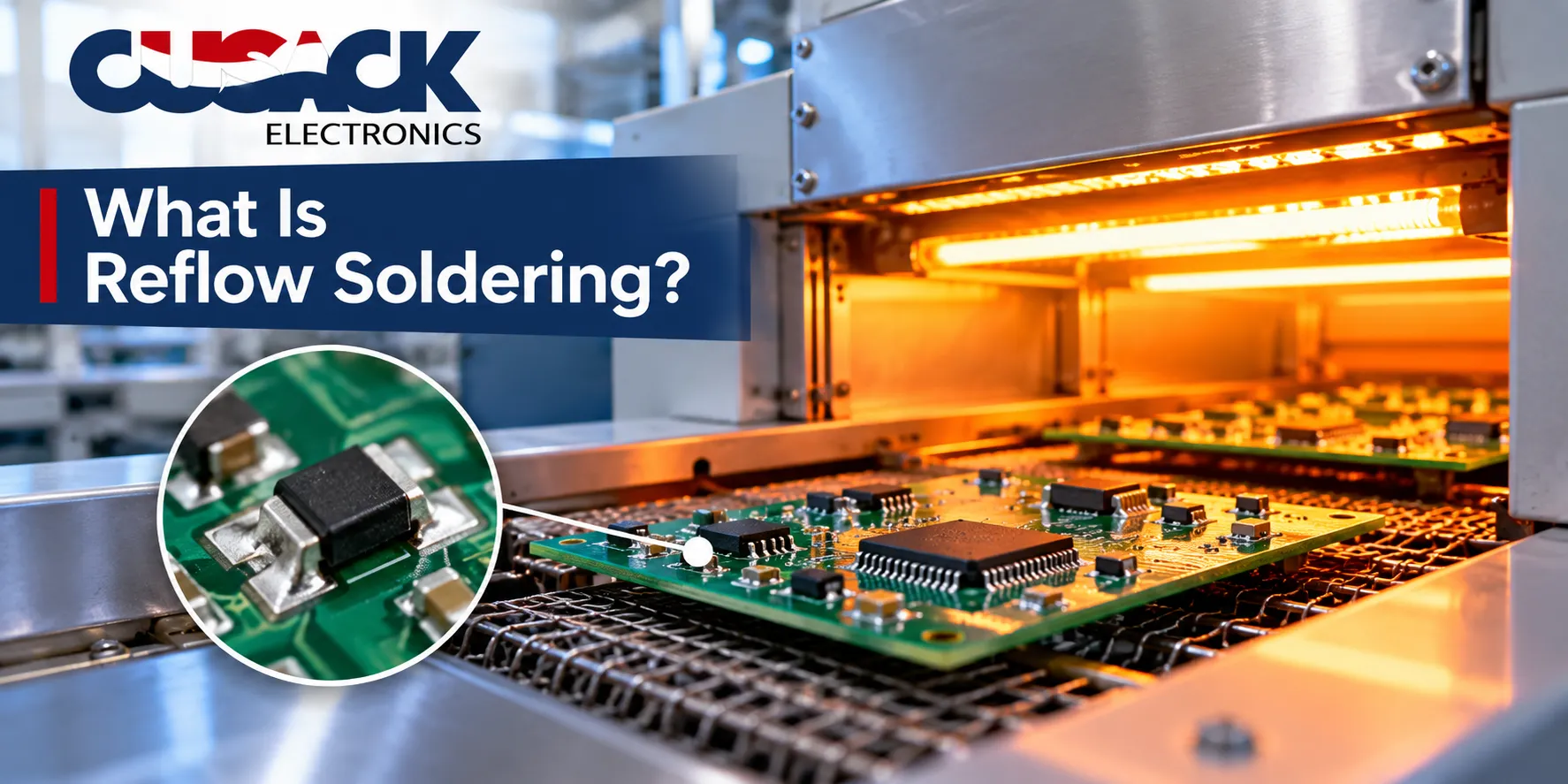
TL;DR: Reflow soldering attaches components to a circuit board by printing solder paste onto the pads, placing parts into it, then heating the whole assembly through a controlled temperature curve until the paste melts and forms every joint at once. That curve is the reflow profile, and it has four stages: preheat, soak, reflow, and cooling. Get the profile wrong and you get cracked parts, cold joints, or tombstoned resistors. The correct profile always comes from the solder paste datasheet, not from a table on the internet.
Reflow soldering is the one step on an assembly line where you cannot see what is happening. The board goes into the oven, it comes out four minutes later, and every joint on it is already decided.
So here is my flat opinion, and it is the reason this article exists: profiling is not a setup task you do once and forget. It is a measurement you take on a real board, with thermocouples attached, every time the board changes in a way that matters.
I have seen more money lost to a profile copied from a similar product than to any other single shortcut in assembly.
What Is Reflow Soldering?
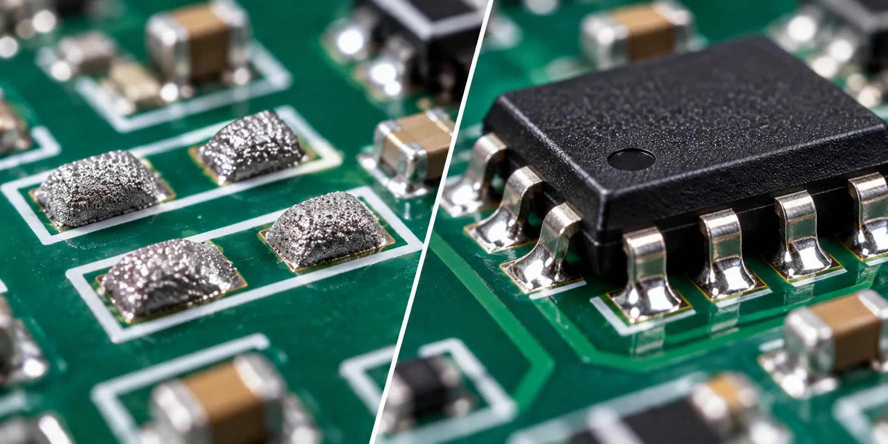
Reflow soldering is a soldering process that melts pre-applied solder paste with controlled heat to form every solder joint on a circuit board simultaneously, rather than one joint at a time.
Think of it like baking rather than welding. You lay out all the ingredients cold, put the whole tray in the oven, and the heat does the assembly work everywhere at once.
The paste itself does two jobs. It is a sticky mixture of powdered solder alloy and flux, so it holds parts in position before heating and cleans the metal surfaces during it.
Wikipedia’s entry puts the definition plainly: solder paste temporarily attaches anywhere from one to thousands of components to their pads, after which the whole assembly is subjected to controlled heat.
Why Is It Called Reflow?
The name comes from what the solder physically does. It was already deposited as a paste, so the oven does not add solder; it re-melts what is there and lets it flow into a joint.
Surface tension does the rest. Molten solder wets the pad and the component lead, pulls tight, and drags slightly misaligned parts into position as it goes. That self-centring effect is why placement tolerance can be looser than the finished joints look.
How Does the Reflow Soldering Process Work?
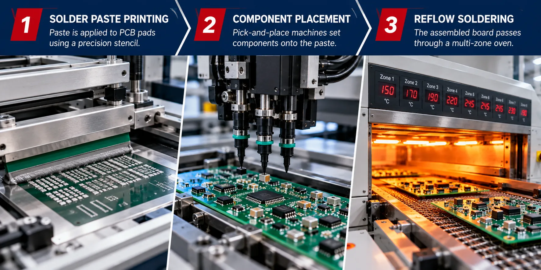
Reflow soldering runs in three moves: print the paste, place the parts, then heat the board. Together, they are a surface-mount assembly, the way almost every modern board is built under surface-mount technology (SMT).
- Stencil printing: a stainless steel stencil with an aperture over every pad and a squeegee that presses solder paste through it.
- Component placement: a pick-and-place machine sets each surface-mount device (SMD) into the wet paste, held only by the tackiness of the flux.
- Reflow: the populated board travels through a reflow oven on a conveyor, following a fixed temperature curve.
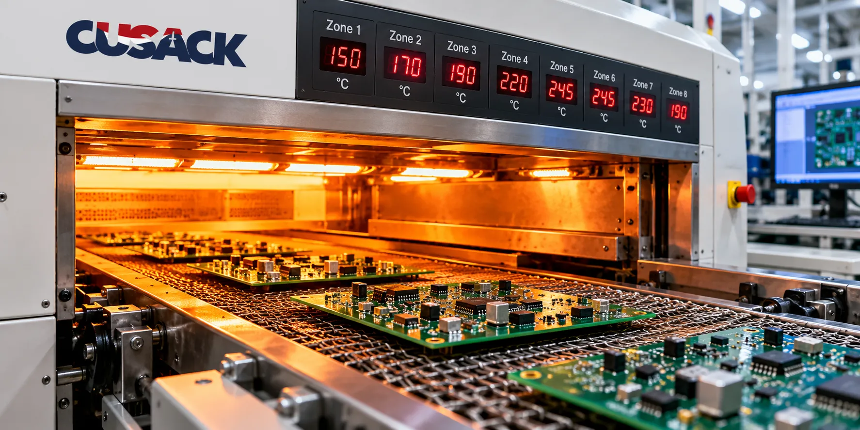
Most production ovens are forced-air convection with eight to twelve independently controlled zones. Infrared and vapour phase ovens exist and still have their uses, but convection is what you will meet on almost any modern line.
This piece covers the oven. For the printing and placement stages ahead of it and the inspection and test stages after, I have walked through the whole line in my guide to the SMT assembly process.
What Is a Reflow Profile?
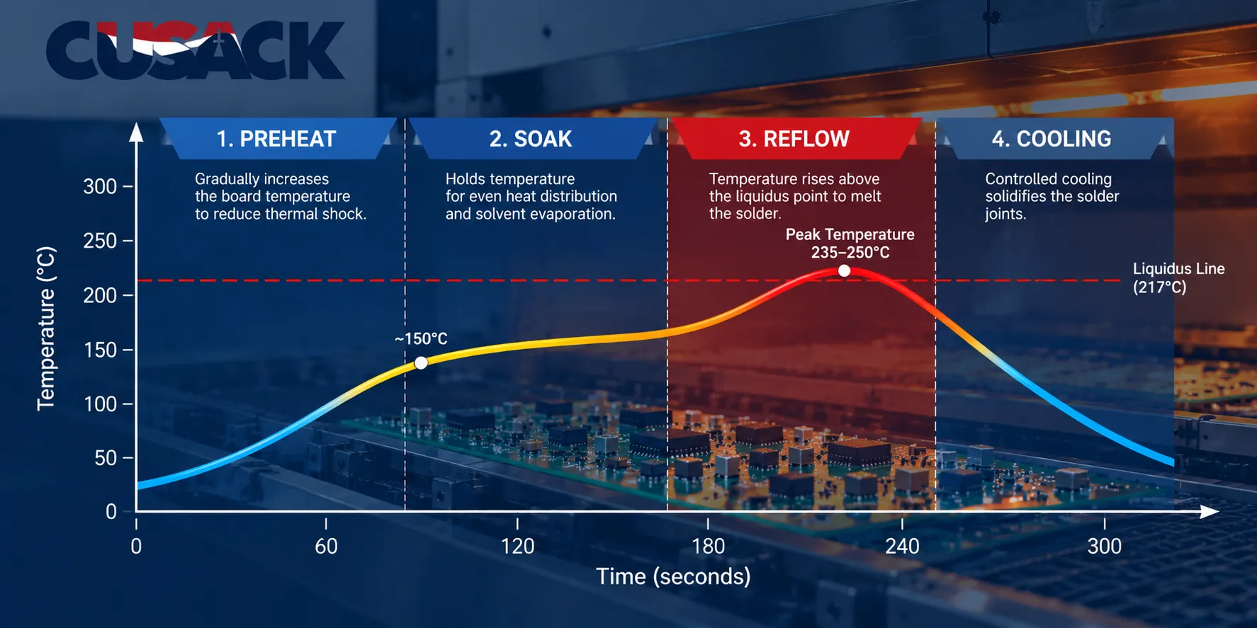
A reflow profile, also called a thermal profile, is the temperature-versus-time curve that a board actually experiences as it passes through the oven, measured on the board rather than set on the machine.
That distinction matters more than anything else here. Zone set points are what you type into the oven. The profile is what the copper, the laminate, and the components actually reach, and the two are never the same.
A heavy board with a large ground plane lags behind a thin one in the same oven at the same speed. Thermal mass is the reason, and it is why board material and thickness change the profile.
If that side of it is new to you, my breakdown of PCB materials covers what the substrate does under heat.
The governing document is IPC-7530B, Guidelines for Temperature Profiling for Mass Soldering Processes, published in 2025 and replacing IPC-7530A from 2017.
What Are the Four Reflow Oven Zones?
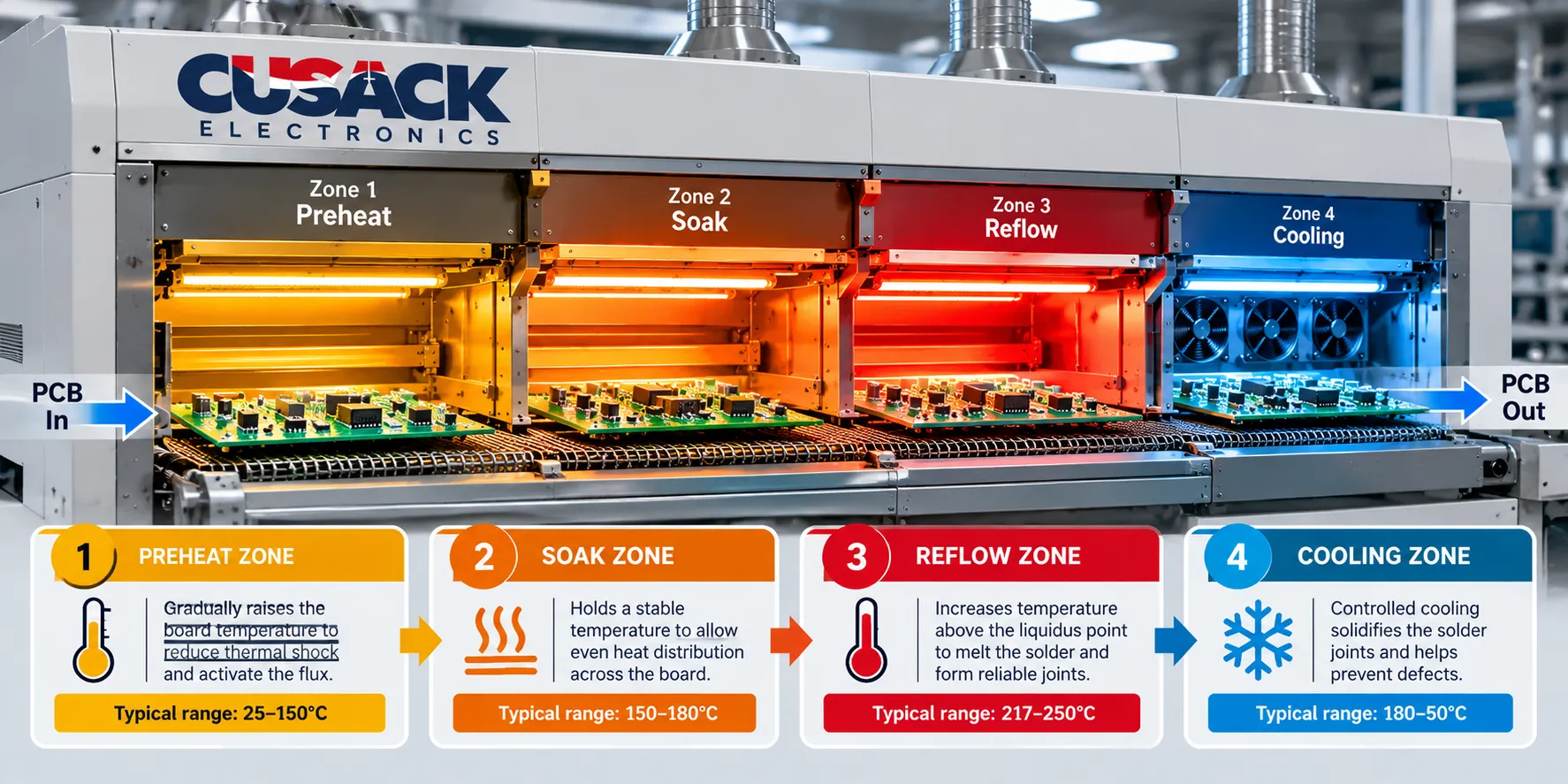
Every reflow profile does four jobs in the same order, and each stage exists to solve a specific problem.
Preheat
Preheat raises the board steadily from room temperature toward the soak band, driving off the volatile solvents in the paste along the way.
The constraint is the ramp rate. Heat too fast and thermal shock cracks ceramic capacitors and can pop moisture-laden plastic packages. Wikipedia gives a maximum slope of 3.0 degrees Celsius per second, and most paste datasheets are more conservative than that.
Too slow is also a failure. The flux has a finite working life once it is warm, and a long crawl through preheat spends it before the solder ever melts.
Soak
Soak holds the board in a band below the melting point so the flux can activate, strip oxide off the pads and leads, and let thermally heavy and light areas of the board even out.
That evening-out is the real purpose. The temperature difference across a board, usually written as delta T, is what separates a joint that forms properly from one that never reaches liquidus at all.
Typical soak durations run 60 to 120 seconds.
Reflow
Reflow is the stage where the board crosses the alloy’s melting point, the solder liquefies, wets the metal surfaces, and forms the joint.
Two numbers define it: peak temperature, and time above liquidus (TAL), the seconds the joint spends fully molten. Wikipedia puts the usual peak at 20 to 40 degrees Celsius above liquidus, with TAL commonly 30 to 60 seconds.
TAL is where most profiling arguments happen. Too short and the solder never wets properly, leaving cold or partial joints. Too long and you grow brittle intermetallic layers and cook the parts.
Cooling
Cooling drops the board temperature at a controlled rate so the molten solder solidifies into a fine grain structure.
Faster cooling generally gives a stronger, shinier joint, because the metal crystals have less time to grow coarse. Faster is not free, though: too steep a drop stresses large components and the board itself. A commonly cited ceiling is around 4 degrees Celsius per second.
Reflow Soldering Temperature Profile: The Numbers
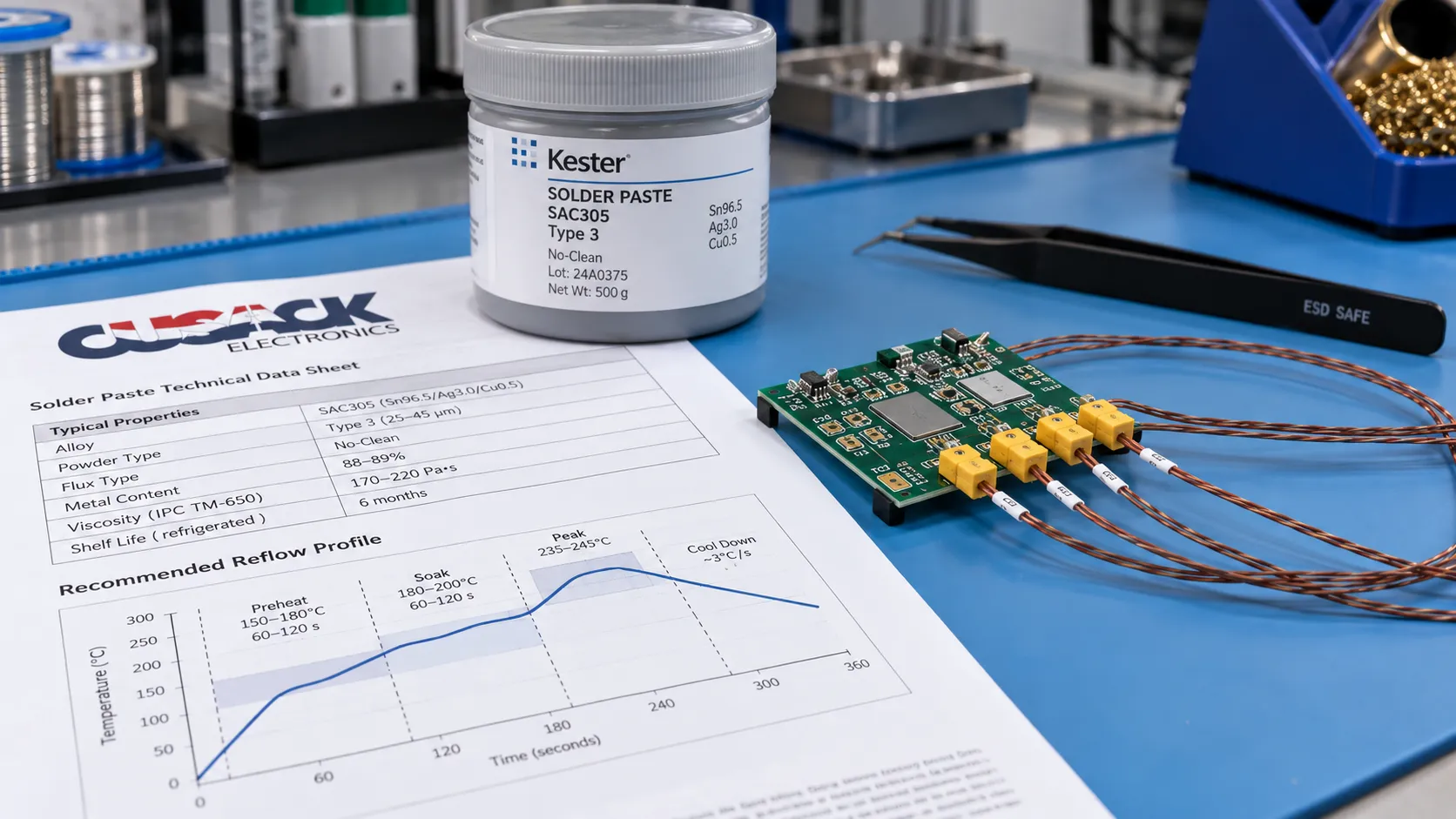
Read this table as a sanity check, not as a recipe. The correct figures for your board are on your paste datasheet, and they differ between manufacturers of the same nominal alloy.
| Stage | Leaded (Sn63Pb37) | Lead-free (SAC305) |
|---|---|---|
| Alloy melting point | About 183 degrees C | About 217 degrees C |
| Preheat ramp | Up to 3 degrees C per second | Up to 3 degrees C per second |
| Soak band | Roughly 150 to 165 degrees C | Roughly 150 to 180 degrees C |
| Soak duration | 60 to 120 seconds | 60 to 120 seconds |
| Typical peak | Roughly 225 to 235 degrees C | Roughly 245 to 255 degrees C |
| Time above liquidus | 30 to 60 seconds | 30 to 60 seconds |
| Cooling rate | Up to about 4 degrees C per second | Up to about 4 degrees C per second |
The headline difference is roughly 20 degrees Celsius of extra peak temperature for lead-free work. That sounds modest. It is not, because the ceiling above the peak did not move with it.
Component packages carry a maximum classification reflow temperature set by IPC/JEDEC J-STD-020F, the moisture and reflow sensitivity standard reissued in 2022. Lead-free profiles run much closer to that ceiling, so the usable window between “properly molten” and “damaged” is narrower.
Ramp-Soak-Spike or Ramp-to-Spike
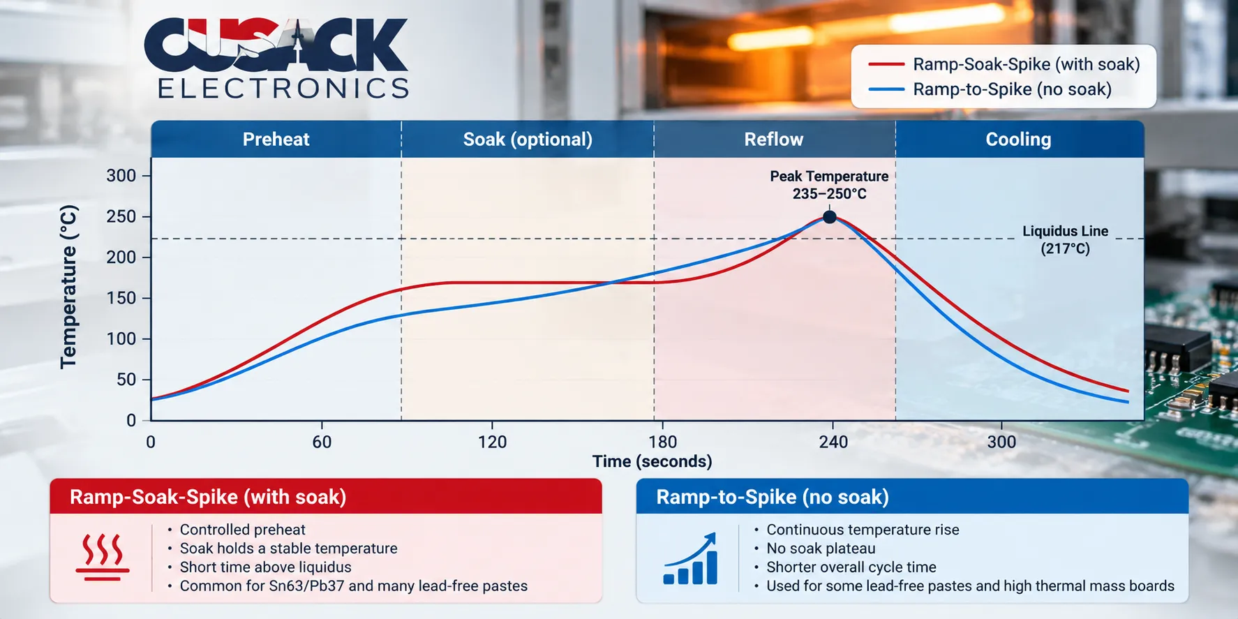
Reflow profiles come in two shapes, and most articles only describe one of them.
Ramp-soak-spike is the classic four-stage curve: climb, flatten into a soak plateau, then spike through the melting point. The flat soak is what evens out temperature across a mixed board.
Ramp-to-spike climbs at a steady slope all the way to the peak, with no plateau at all. It is shorter, gentler on flux, and works well on boards where every part has a similar thermal mass.
Which to use is a judgement about your board, not a preference.
- Choose ramp-soak-spike when the board mixes heavy and light parts, has thick copper, or runs close to a component temperature limit.
- Choose ramp-to-spike when the board is thermally uniform and you want less total heat exposure.
- A slanted soak sits between the two: the soak band rises gently instead of holding flat, trimming the peak difference across the board.
I default to ramp-soak-spike on anything with a mix of connectors and fine-pitch parts. The delta T control is worth the extra flux exposure.
How Do You Build a Reflow Profile?
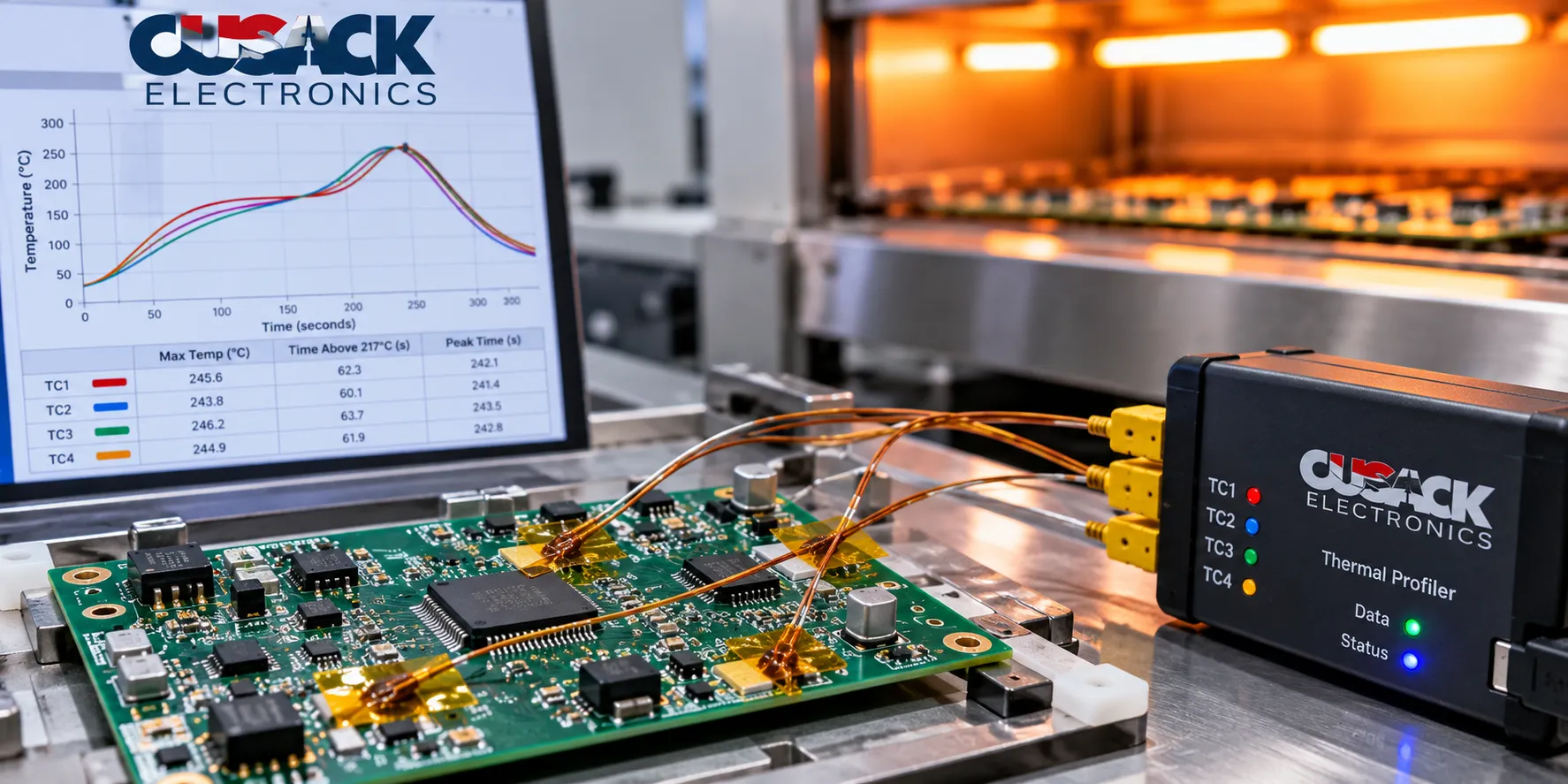
Build a reflow profile by measuring a real board, not by copying zone settings. The sequence is short, and skipping any of it is where the cost comes from.
- Read the paste datasheet. It specifies the ramp, soak band, peak window, and time above liquidus that the paste chemistry is formulated for.
- Find the component ceiling. The least tolerant package on the board sets the maximum peak, per its classification reflow temperature.
- Attach thermocouples. Fix them to the extremes: the largest thermal mass, the smallest part, and a bare area of laminate. Those points bracket your delta T.
- Run the board and log it. A profiler travels through the oven with the board and records what each thermocouple saw.
- Adjust zone temperatures and conveyor speed. Speed changes how long the board spends in every zone at once, so change one variable at a time.
- Re-run until every thermocouple sits inside the paste window. Not the average. Every one.
Where to put the thermocouples is the part people get wrong. Attach them to the coldest spot you can identify, usually next to a large ground pour or under a big component, because that is the joint that fails to form while everything else looks fine.
Re-profile when the board material changes, when a large component is added or removed, or when you move the job to a different oven. A profile is specific to one board on one machine.
What Happens When the Profile Is Wrong?
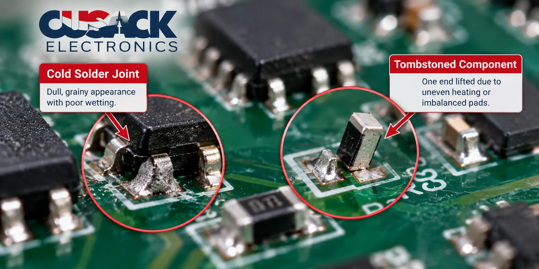
Most reflow defects point back to one specific part of the curve, which is what makes them diagnosable rather than mysterious.
| Defect | What you see | Profile cause |
|---|---|---|
| Cold joint | Dull, grainy, poorly wetted | Peak too low or time above liquidus too short |
| Tombstoning | A two-lead part standing upright on one end | Uneven heating across the two pads during reflow |
| Component cracking | Fractured package, often invisible from outside | Preheat ramp too steep, or a moisture-laden part |
| Voiding | Gas pockets inside a joint, visible only on X-ray | Flux outgassing trapped by too fast a climb through reflow |
| Solder balling | Small spheres scattered beside the joint | Preheat too fast, spattering the paste |
| Brittle joints | Cracking under vibration or thermal cycling | Time above liquidus too long, growing thick intermetallics |
| Warped board | Bowed laminate, joints pulled open | Excessive peak or an uneven temperature gradient |
Notice that both ends of the curve can produce a failure. That is the point of profiling: you are not maximising heat, you are steering between two limits.
Reflow, Wave, or Vapour Phase?
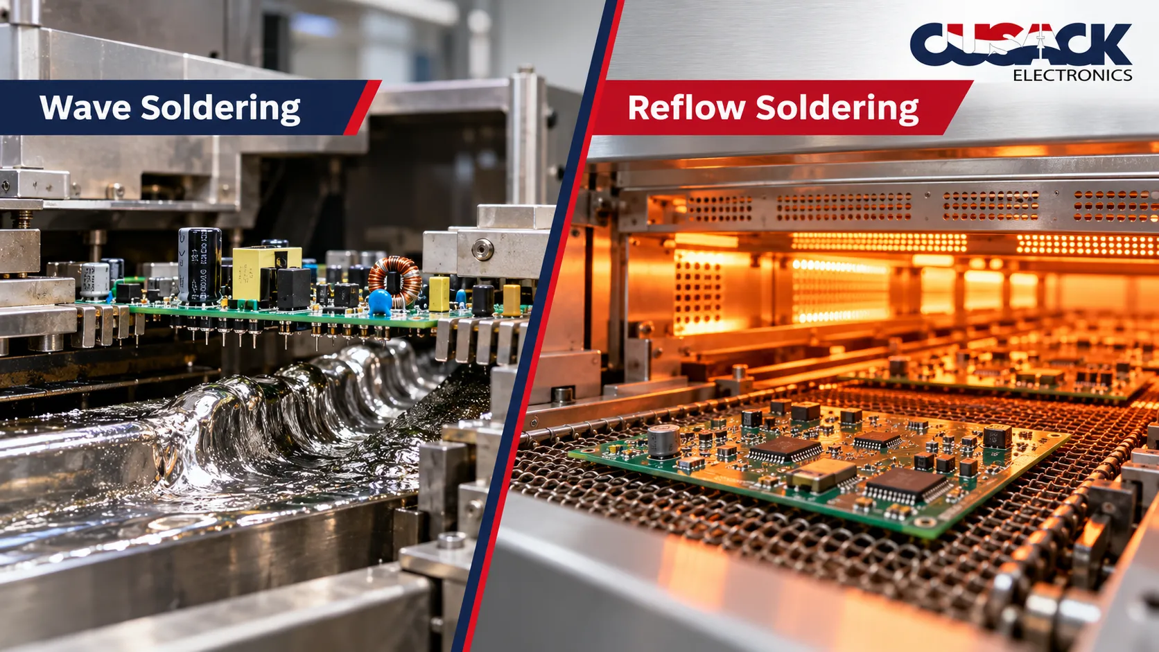
Reflow is not the only way to solder a board, and the three methods do not compete so much as cover different parts.
- Reflow soldering melts paste already printed on the pads. It is the soldering method of surface-mount technology, and it forms the overwhelming majority of joints on a modern board.
- Wave soldering runs the board over a standing wave of molten solder, wetting leads that pass through the board. It suits through-hole parts and boards with many of them.
- Vapour phase heats the board in the vapour of a boiling inert fluid, so the board can never exceed that fluid’s boiling point. That temperature ceiling is the attraction on sensitive assemblies.
Most real boards carry both surface-mount and through-hole parts, so they see reflow first and then selective or wave soldering for the leaded components. I have compared the two technologies properly in SMT vs through-hole.
Frequently Asked Questions
What temperature is reflow soldering?
It depends on the alloy. Lead-free SAC305 melts near 217 degrees Celsius and usually peaks around 245 to 255, while leaded Sn63Pb37 melts near 183 and peaks around 225 to 235. The correct peak for your board comes from the paste datasheet and the temperature limit of the least tolerant component on it.
How long does reflow soldering take?
A typical profile runs four to six minutes from the board entering the oven to leaving the cooling zone. Conveyor speed sets that total, and changing it shifts the time spent in every zone at once, which is why speed is adjusted carefully.
What is time above liquidus?
Time above liquidus is the number of seconds a solder joint spends fully molten during reflow. It commonly sits between 30 and 60 seconds. Too little and the solder does not wet the surfaces properly; too much and the joint grows brittle intermetallic layers.
Can a board go through reflow twice?
Yes, and double-sided boards do exactly that, bottom side first. Each pass is more heat exposure for every surface-mount device on the board, though, so a third or fourth pass needs checking against the component ratings rather than assuming it is fine.
Do I need to bake components before reflow?
Only moisture-sensitive SMDs whose exposure clock has run out. Plastic packages absorb moisture from the air, and heating that moisture fast enough turns it to steam inside the package and cracks it. The rating on the bag tells you the floor life.
Why is my board fine on one machine and failing on another?
Because a profile belongs to a board and an oven together, not to the board alone. Different ovens have different zone counts, airflow, and thermal response, so a profile that passes on one is a starting point on the next, not a finished setting.