What You Learn in 30 Seconds
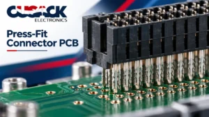
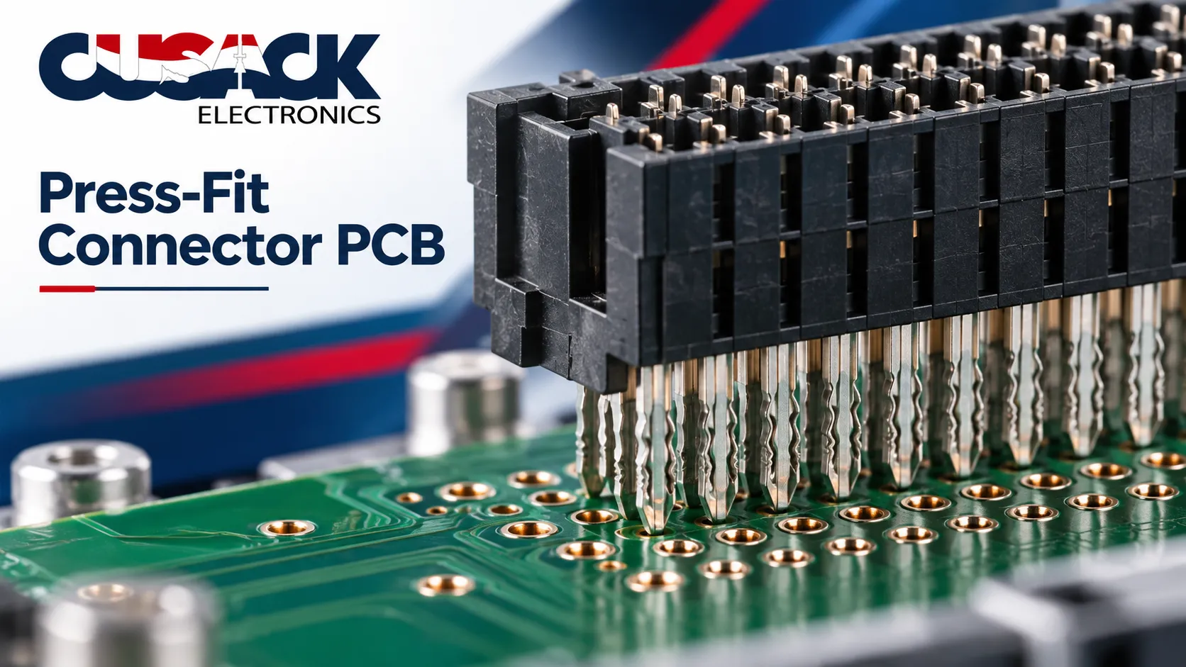
A press fit connector pcb uses connector pins forced into plated through holes and held by mechanical interference, with no solder anywhere in the joint.
Two standards govern it: IEC 60352-5 Edition 5.0 from 2020 and IPC-9797 from the same year, with IPC’s companion handbook revised as recently as January 2026.
The pin is the easy part. The hole is where this technology succeeds or fails, and the tolerance window is roughly half what a normal plated through hole gets.
Press-fit gets sold as the simple option. No solder, no oven, no flux, fewer process steps.
That framing is half true and it causes trouble. Press-fit does not remove difficulty, it moves it upstream into the bare board, where a hole either falls inside a tight window or does not.
My position: I will specify it on anything carrying a backplane-style connector at volume, and I push back whenever someone calls it the easy path. Your fabricator inherits the risk you just took off the soldering line, and they need telling before they quote.
What Is a Press-Fit Connector?
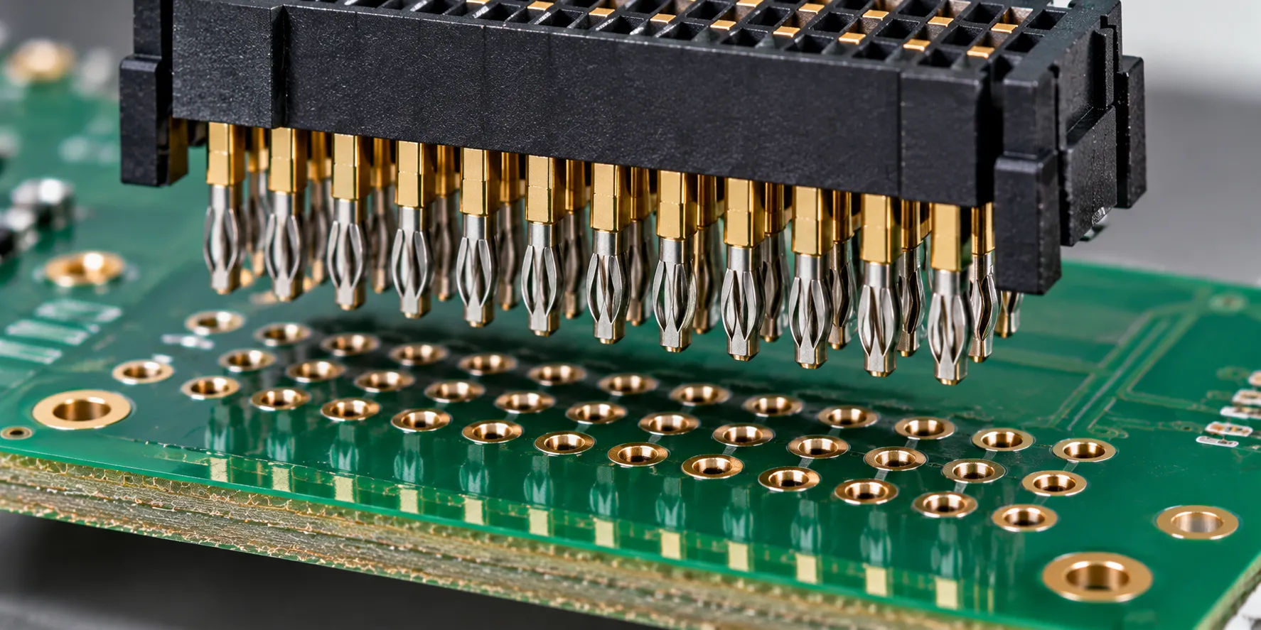
A press-fit connector is a connector whose pins are pressed into plated through holes and retained by interference alone, with no solder in the joint. That makes it a solderless connector in the strict sense: there is no alloy anywhere in the joint.
Press fit technology arrived through the telecom industry in the 1970s, for backplane work where hundreds of connections had to be made at once and reworked later.
IEC defines the joint itself precisely. A press-in connection is a “solderless connection made by inserting a press-in termination into a hole of a board”, and the termination is a pin with “a specially shaped zone suitable to provide for a solderless press-in connection”.
Those definitions come from IEC 60352-5 Edition 5.0, which replaced the 2012 fourth edition.
Picture a wall plug. The plug is slightly larger than the drilled hole, so driving it in forces both parts into permanent contact. A press-fit pin works the same way, with one refinement that matters enormously.
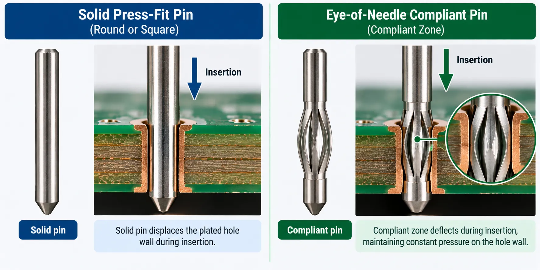
Two families exist, and the difference decides what gets damaged:
- Solid or rigid pins do not deform. The hole absorbs all the interference, which is hard on the plated barrel and limits the technology to simpler boards.
- Compliant pins carry a deformable press-in zone that collapses elastically during insertion, so the pin takes most of the strain instead of the barrel.
The eye-of-needle pin is the compliant shape most people recognise: a flattened oval opening through the middle of the pin, which squeezes closed as it enters the hole and keeps pushing outward afterwards.
That residual outward push is the whole mechanism. A compliant pin is a spring that never stops pressing.
How Does a Press-Fit Connection Actually Hold?
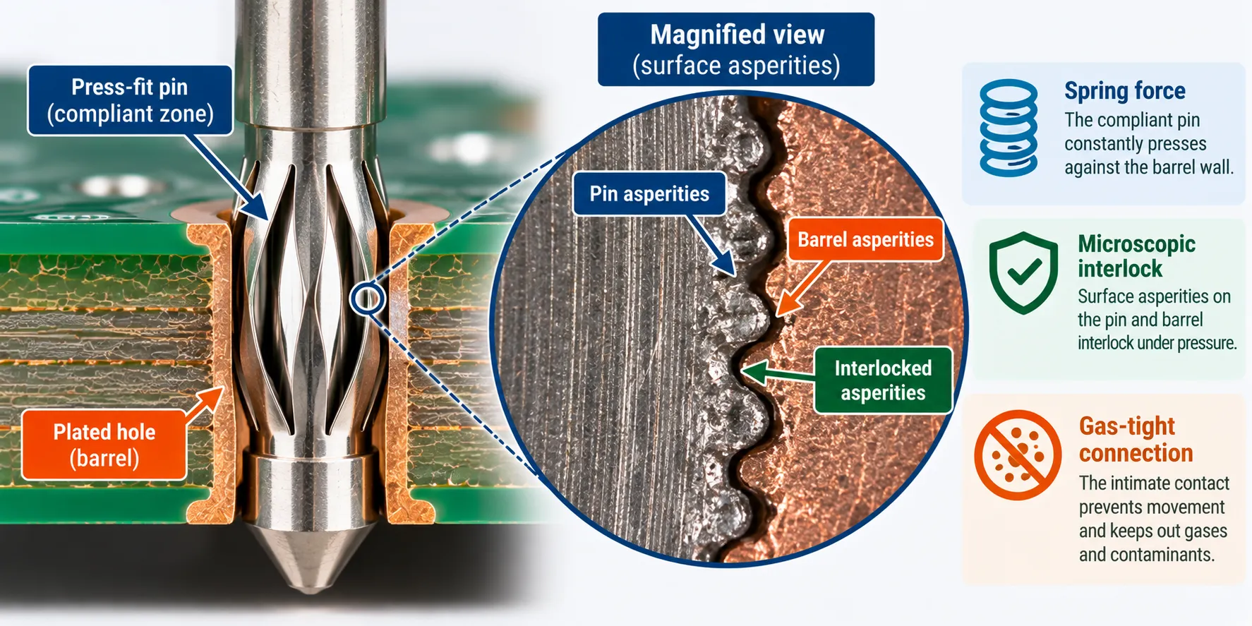
It holds because the compliant zone keeps pressing pin metal against barrel metal hard enough that the two surfaces interlock and no air reaches the contact area.
The industry calls the result a gas-tight connection. IPC uses a more literal term in its own vocabulary, “intimate metal to metal connection”, which describes the physics better than the marketing phrase does.
The mechanism is surface roughness. Every metal surface is microscopically rough, and IPC’s press-fit handbook devotes a section to contact physics with a figure titled “Interlocking of Asperities Between Surfaces”.
That handbook is IPC-HDBK-9798A, issued January 2026, superseding the 2022 original.
Press two rough metal surfaces together hard enough and the high points on each deform into the valleys of the other. The contact stops being two surfaces touching and becomes something closer to a single piece of metal across thousands of tiny welded points.
That is also why the joint does not corrode from the inside. Oxygen cannot reach the interface, so there is no oxide layer forming between the pin and the barrel over the product’s life.
Lose the spring force and you lose all of it at once. This is why the compliant zone’s material and geometry matter more than the plating does.
What Hole Size and Tolerance Does a Press-Fit Pin Need?
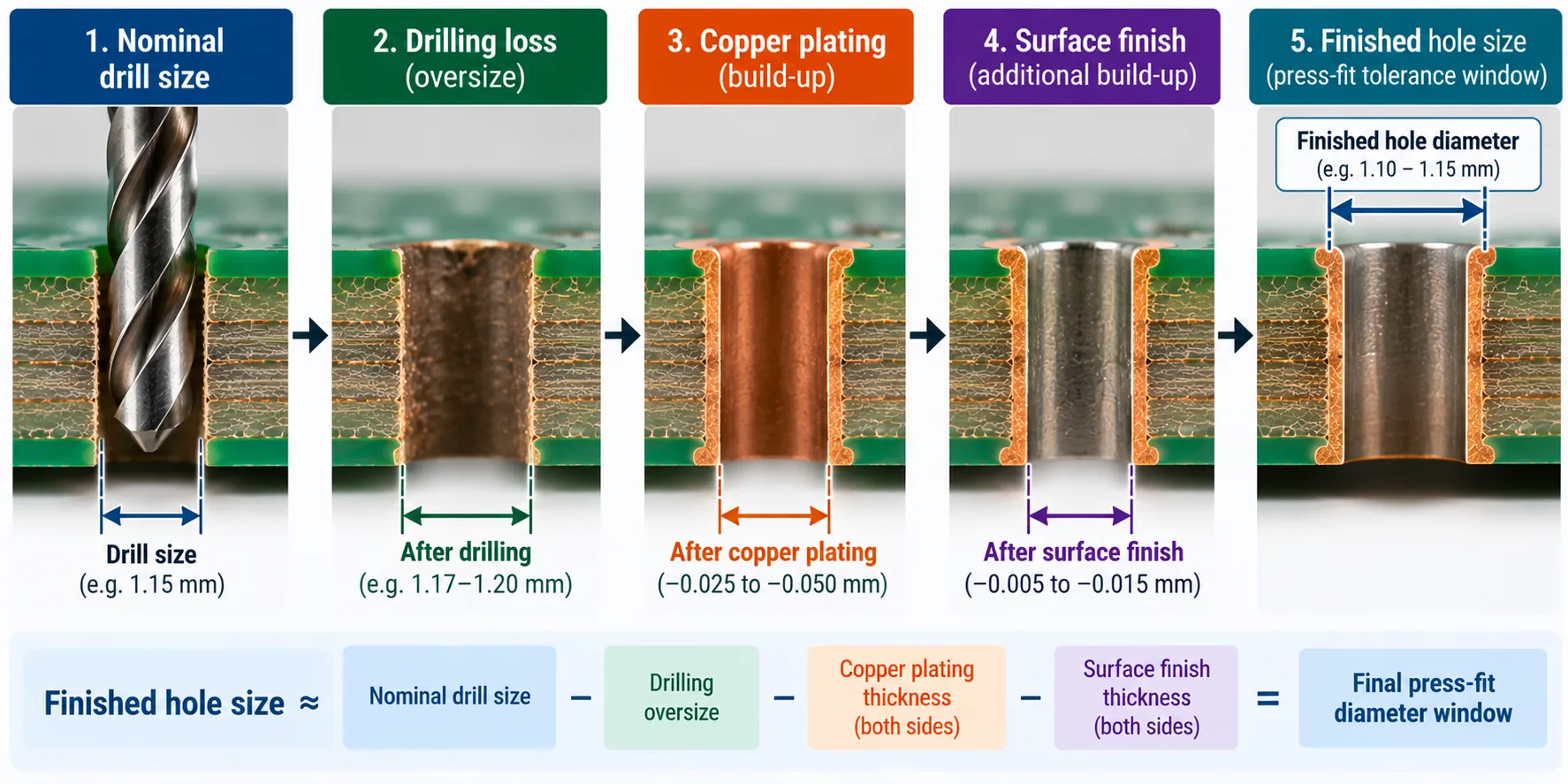
Specify the finished hole, never the drill size, and expect a tolerance window around half what an ordinary plated through-hole is given.
Press fit pcb hole size is the single most common and most expensive mistake on this technology. A drill diameter and a finished hole diameter are separated by three subtractions, and every one of them varies.
Work through it with the figures a connector manufacturer publishes for its press fit pin ranges:
- Drilling undercuts. A drilled hole in FR-4 finishes roughly 0.0005 inch below the nominal drill size.
- Copper plating subtracts more. Half an ounce to one ounce of copper takes another 0.0015 to 0.003 inch off the diameter.
- The surface finish subtracts again. Between drilled and finished, expect a total loss of 0.003 to 0.005 inch depending on which finish goes on.
- The window is tight. Press fit pin hole tolerance on the finished hole is about plus or minus 0.002 inch.
Those figures come from Mill-Max application guidance for press-fit pins in plated through holes.
The same note carries a warning worth repeating. Barb and knurl retention features are not recommended for multilayer plated through holes, because they cut into the barrel rather than pressing against it.
A connector maker’s published FR-4 specification puts the same thing in metric:
- Nominal hole 1.0 mm, finished to 1.0 mm with a plus 0.09 and minus 0.06 tolerance
- Base hole 1.15 mm, plus or minus 0.025 mm
- Copper at least 25 micrometres, residual ring at least 0.1 mm
- Board no thinner than 1.44 mm
That is from ept’s press-fit fundamentals paper. The board thickness line is the one people miss, because a press-fit pin needs barrel length to grip.
Put the finished hole window on the fabrication drawing, flag the holes as press-fit, and treat it as a design for manufacturability item rather than a detail the fab will infer.
Which PCB Surface Finish Works With Press-Fit?
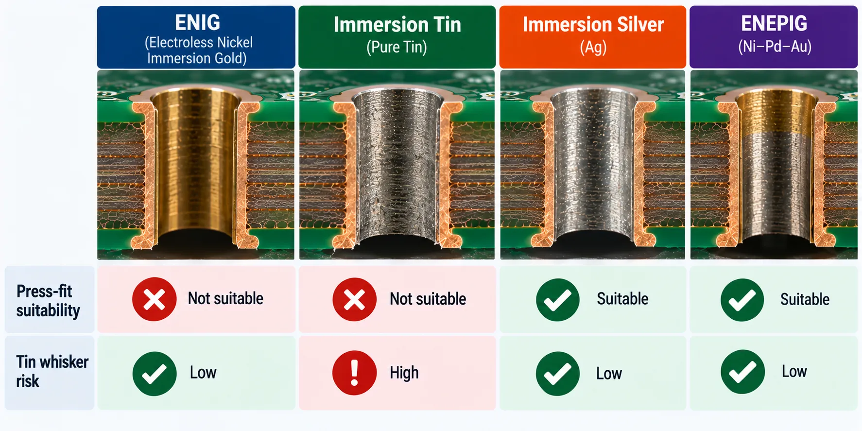
Immersion tin, and that answer creates a problem on exactly the boards most likely to want press-fit in the first place.
Connector manufacturers publish finish ratings, and they are not close. One rates immersion tin as very good for press-fit, OSP as good, and then puts ENIG, immersion silver and lead-free HAL all in a limited category that depends on the application.
ENIG being the weak one matters, because ENIG is the default premium finish on most high-reliability boards. The nickel underlayer is hard, and a press-fit pin wants a surface that yields a little.
Now the opposite pull. A CNES and Positronic evaluation of press-fit connectors for spacecraft excluded pure tin finishes entirely over tin whisker risk, and used 5 micrometre gold over nickel instead.
Their work is published through the European Space Agency.
So the finish that presses best is the one a whisker-sensitive application will not accept, and the finish that application demands is the one rated limited for pressing. Tin whiskers are covered properly in my guide to lead-free vs leaded solder.
I do not think there is a clean answer here. It is an application judgement, and anyone who tells you otherwise is selling one of the two finishes.
Press-Fit vs Soldering: Which Should You Use?
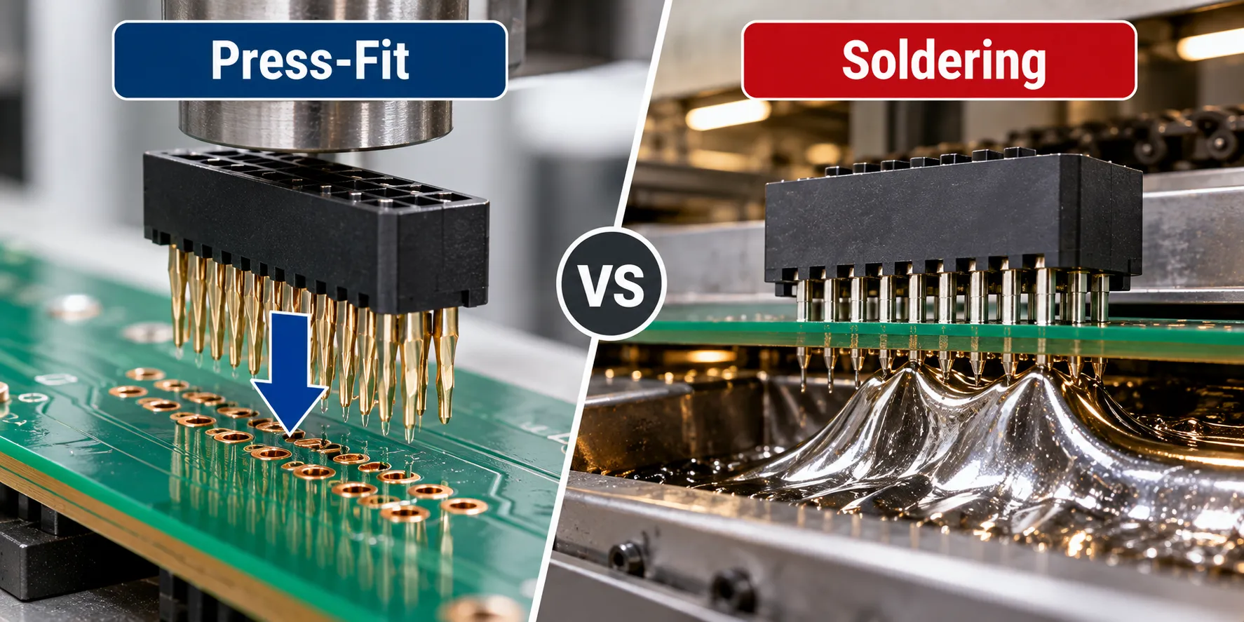
The press fit vs soldering decision turns on size and volume. Choose press-fit when the connector is large, the board is already built, and the quantity justifies tooling. Choose soldering when it is not.
| Press-fit | Soldered connector | |
|---|---|---|
| Joint formed by | Sustained spring force | Melted alloy |
| Board thermal exposure | None at attach | Full wave or reflow cycle |
| Hole tolerance | About plus or minus 0.002 inch | Standard plated through hole |
| Tooling | Press, support block, specific tools | None beyond the soldering line |
| Rework | Possible, limited cycles | Normal rework |
| Added process step | A pressing operation | None, it joins existing flow |
Before the advantages, one honest warning about the numbers in circulation.
Two vendor sources give press-fit reliability figures that disagree with each other by a factor of ten.
One claims press-fit is at least ten times more reliable than soldered connections. Another publishes 0.005 failures in time against 0.5 for solder, which is a hundredfold gap rather than a tenfold one.
Neither shows its data and neither states test conditions. The one standard reference I could trace behind these claims did not resolve to a document I could verify, so do not build a business case on either figure.
The advantages that survive scrutiny are structural rather than statistical:
- No thermal exposure at attach. The connector goes on after the board is soldered, so it never sees a reflow soldering profile.
- No solder joint to fatigue. A spring contact does not crack the way a rigid alloy joint does under vibration or thermal cycling.
- It removes work from the soldering line. Big connectors are awkward in wave soldering, and press-fit takes them out of it entirely.
- It suits mixed boards. A plated through-hole connector on an otherwise surface-mount board is the classic case, which is the territory covered in SMT vs through-hole.
- It scales to high pin counts. A backplane carrying several hundred connections in one pressing operation is where the economics work best.
The costs are real too. You need a press and part-specific tooling, the press force is substantial, and the hole tolerance shows up in the bare board quote rather than the assembly quote, which makes it easy to miss in PCB assembly cost comparisons.
Can You Rework a Press-Fit Connector?
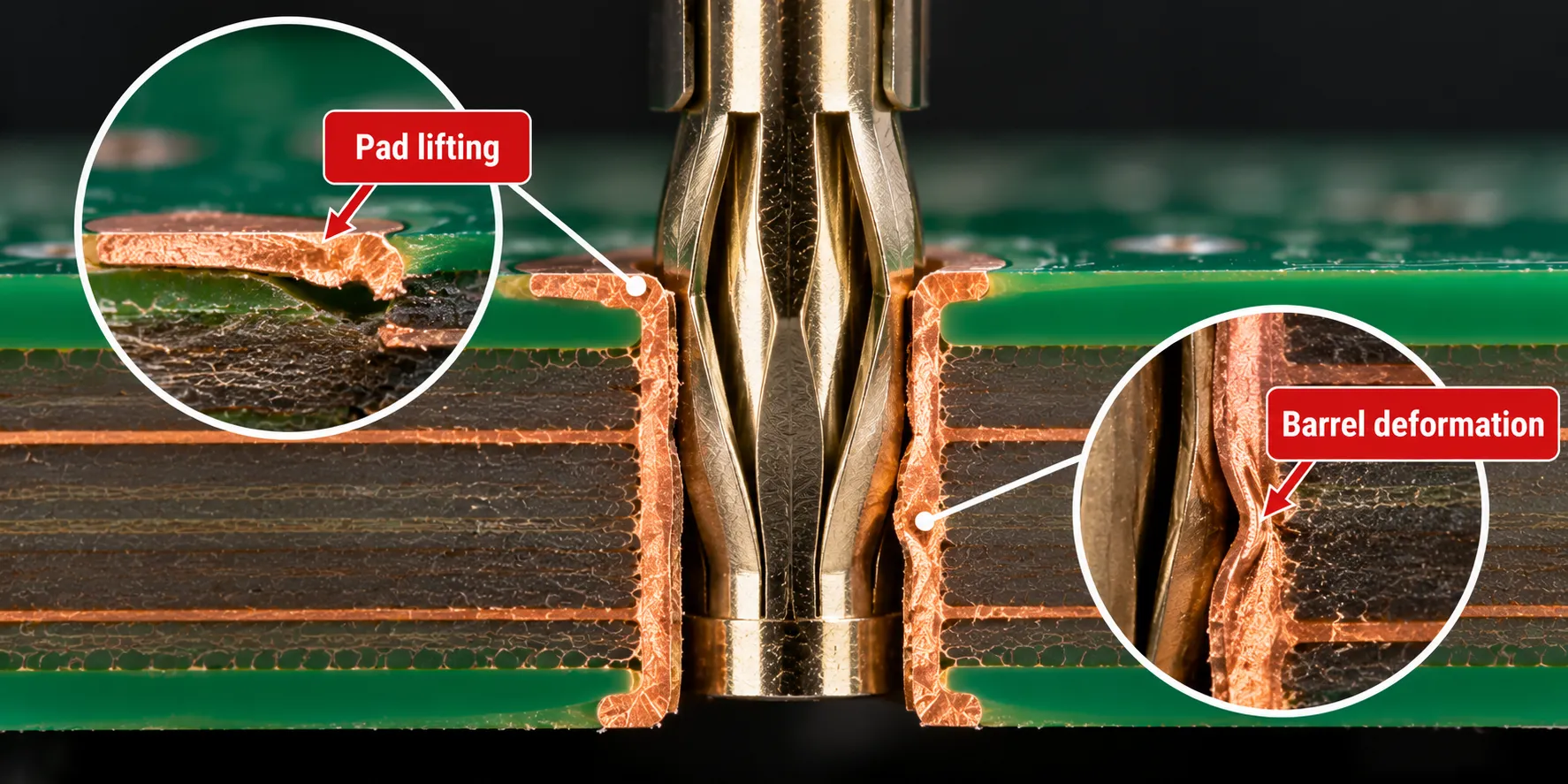
Yes, but fewer times than the sales material suggests, and the damage you need to worry about is mostly invisible from the top of the board.
Both governing documents treat this as a real subject rather than an afterthought. IEC 60352-5 carries guidance on repairing press-in connections in its practical annex, and IPC’s handbook gives rework a full section including a step for validating that a design is reworkable at all.
The hard number I could find comes from the spacecraft evaluation above: those connectors were rated for removal and re-insertion up to two times. Press-out damages the barrel, and each cycle spends margin.
What makes this difficult is that press-fit failure modes hide.
IPC-9797 defines a vocabulary for them that is worth knowing even if you never buy the standard:
- Pad lifting and pad bulging, where the land deforms away from the laminate.
- Laminate buckling, where the board material itself gives way around the hole.
- Whitening, the visible stress marking in the laminate.
- Jet-effect deformation, where barrel material extrudes ahead of the pin.
Most of those are found by microsection, not by looking. If a press-fit joint matters, the qualification route is cross-sections and contact resistance, not visual inspection, which is the same lesson as mechanical damage during PCB depaneling.
The Bottom Line
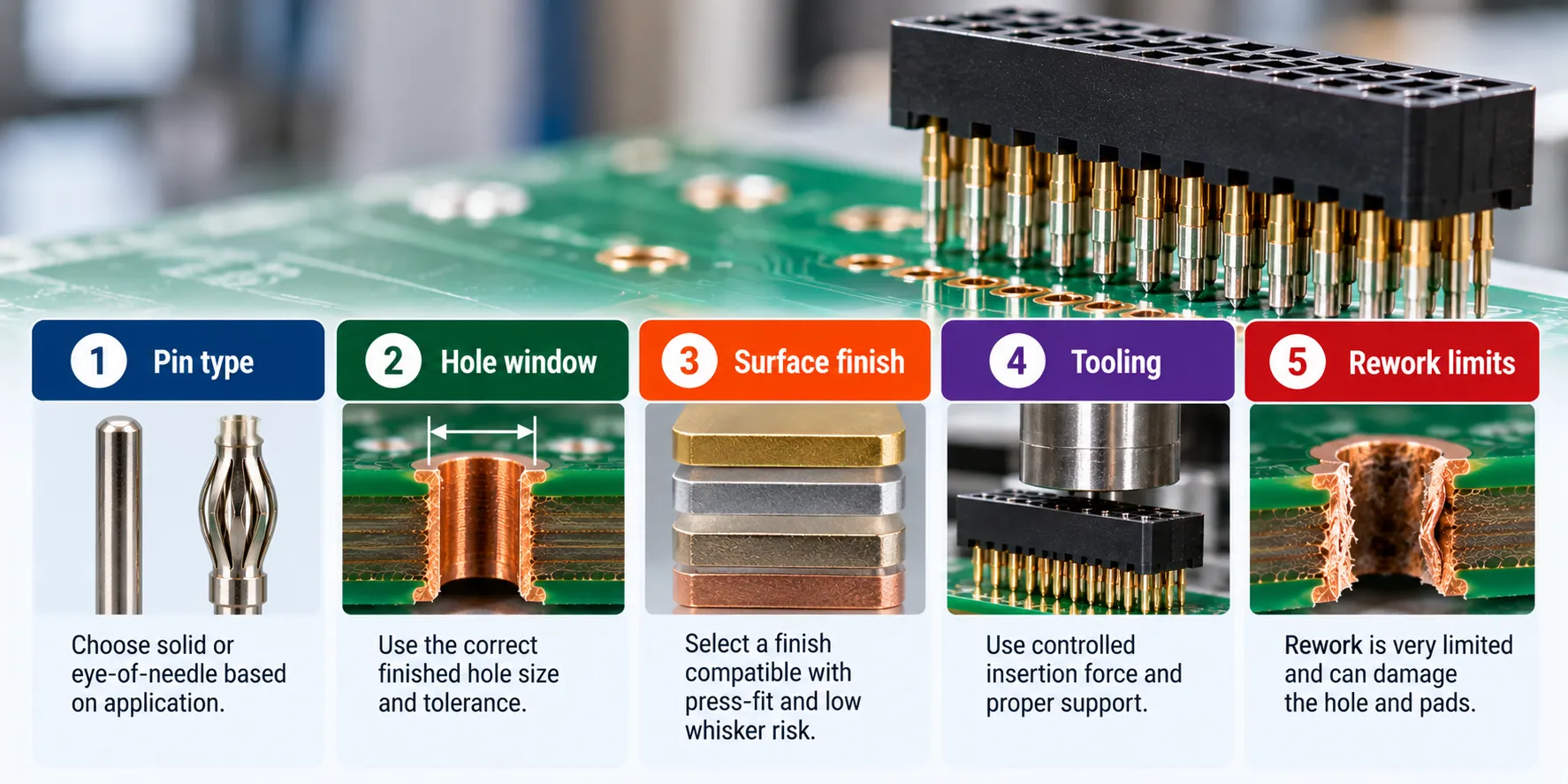
- Press-fit joins a connector to a board by interference, with no solder in the joint.
- Compliant pins deform so the barrel does not. Solid pins do the opposite.
- The joint holds by sustained spring force interlocking the metal surfaces, which is why no air reaches the contact.
- Specify the finished hole, not the drill. Expect about plus or minus 0.002 inch.
- Immersion tin presses best. ENIG, the usual high-reliability default, is rated only limited.
- Rework is possible and limited. Two insertion cycles is a figure with evidence behind it.
- The reliability multipliers quoted in vendor material are unsourced and disagree with each other.
Press-fit is a good technology with a bad reputation for being easy. If you are specifying it on a new board, the conversation to have is with your fabricator about the hole, and it should happen before the first PCB assembly quote rather than after.
Frequently Asked Questions
What do the press-fit standards actually require?
Two documents govern this. IEC 60352-5 Edition 5.0, published July 2020, replaced the fourth edition from 2012 and covers requirements, test methods and practical guidance for press-in connections.
IPC-9797, published May 2020, is the automotive and high-reliability standard, and its companion handbook IPC-HDBK-9798A was issued in January 2026, superseding the 2022 original.
Can press-fit and soldered connections share one board?
Yes, and this is normal practice rather than a compromise. IEC 60352-5 addresses the combination directly in its practical guidance annex, alongside a note on bimetallic corrosion where dissimilar metals meet.
The sequencing is what matters. The board is soldered first and the press-fit connector goes on afterwards, because pressing a connector into a board and then running it through an oven defeats the point.
What force does inserting a press-fit connector take?
It scales with pin count and pin size. Published figures for single pins run from tens to low hundreds of newtons, and one trade account puts a connector of more than a hundred pins at roughly 500 pounds-force in total.
So this needs a press with a properly designed support block underneath, not a bench vice. Uneven support is how boards crack.
Does press-fit work on thin boards?
Not well, because the pin needs barrel length to grip. One connector manufacturer’s FR-4 specification sets a minimum board thickness of 1.44 mm for a 1.0 mm nominal hole, and thin boards also buckle more readily under insertion force.
What is an eye-of-needle pin?
It is the most common compliant press-fit geometry, named for the elongated opening through the middle of the press-in zone, which lets the two sides of the pin squeeze together during insertion.
Because that deformation is elastic rather than permanent, the pin keeps pushing outward against the barrel for the life of the joint.
Is press-fit better for automotive?
It is widely used there, and IPC-9797 was written specifically for automotive and other high-reliability applications, which tells you where the industry’s attention went.
The reasons are vibration tolerance and the absence of a solder joint to fatigue, not any verified reliability multiplier. Qualification still has to happen on your own assembly.