THE 30-SECOND VERSION
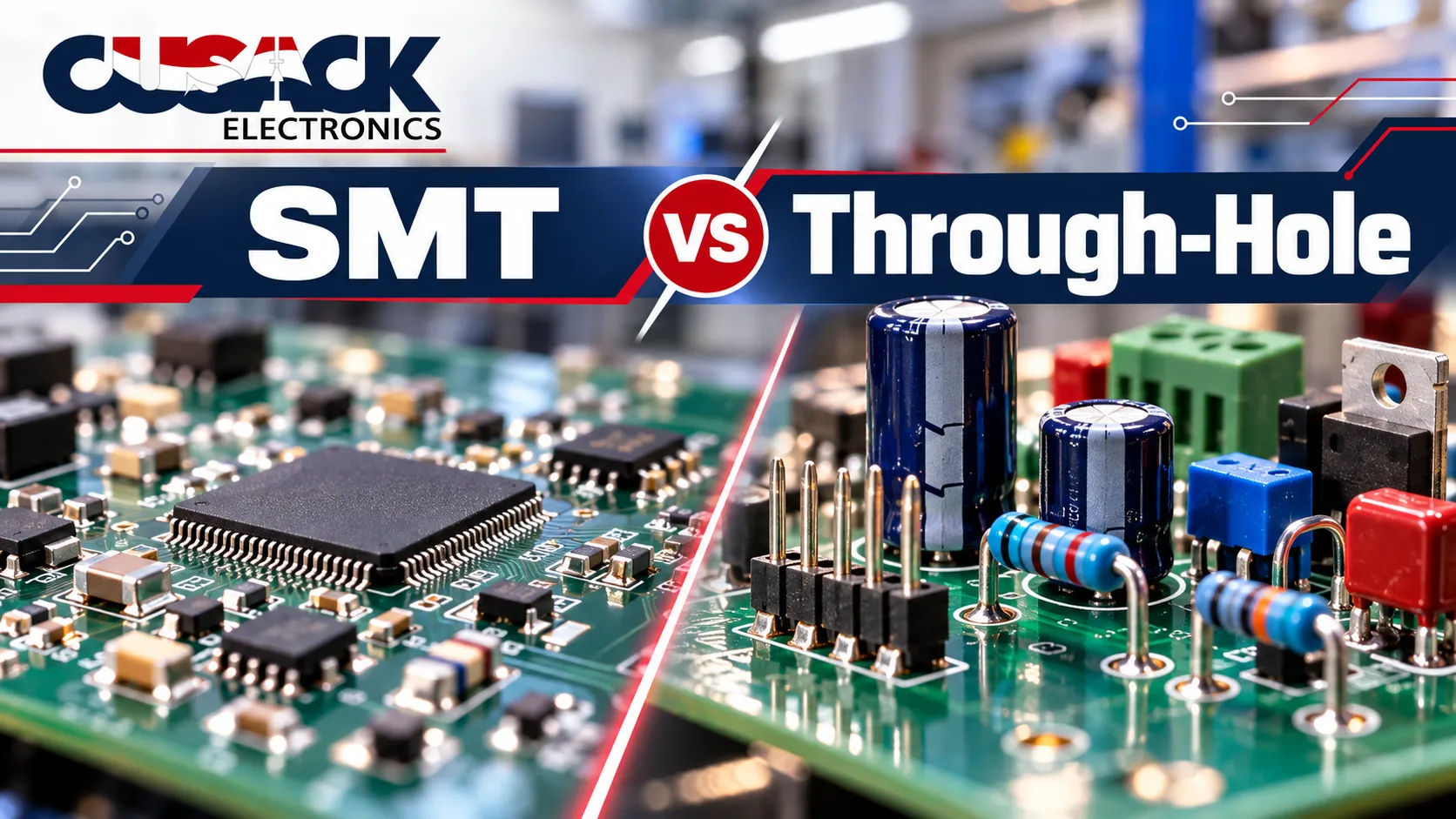
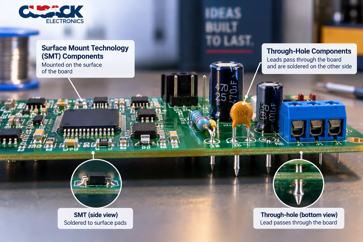
- SMT vs. through-hole is about how a part attaches to the board. SMT parts sit on surface pads. Through-hole parts push their leads through drilled holes and are soldered on the far side.
- SMT wins on size, speed, and cost at volume. It is how the great majority of modern electronics is built.
- Through-hole wins where a part gets pulled, pushed, or is heavy. Connectors, switches, transformers, and big capacitors still go through the board.
- “Through-hole is more reliable” is only half true. It resists pull-out force better, but light SMT parts often handle vibration better.
- Most real boards use both. The useful question is not which method, but which parts go through the board.
SMT vs through-hole is one of the first design decisions on any printed circuit board, and one of the most misunderstood. Plenty of engineers still carry a rule of thumb from school: surface mount for small, through-hole for tough.
Here is my position before the details: “which is better” is the wrong question. Most real boards use both, so the decision that matters is part by part, and the rule of thumb gets several of those parts wrong.
What Is the Difference Between SMT and Through-Hole?
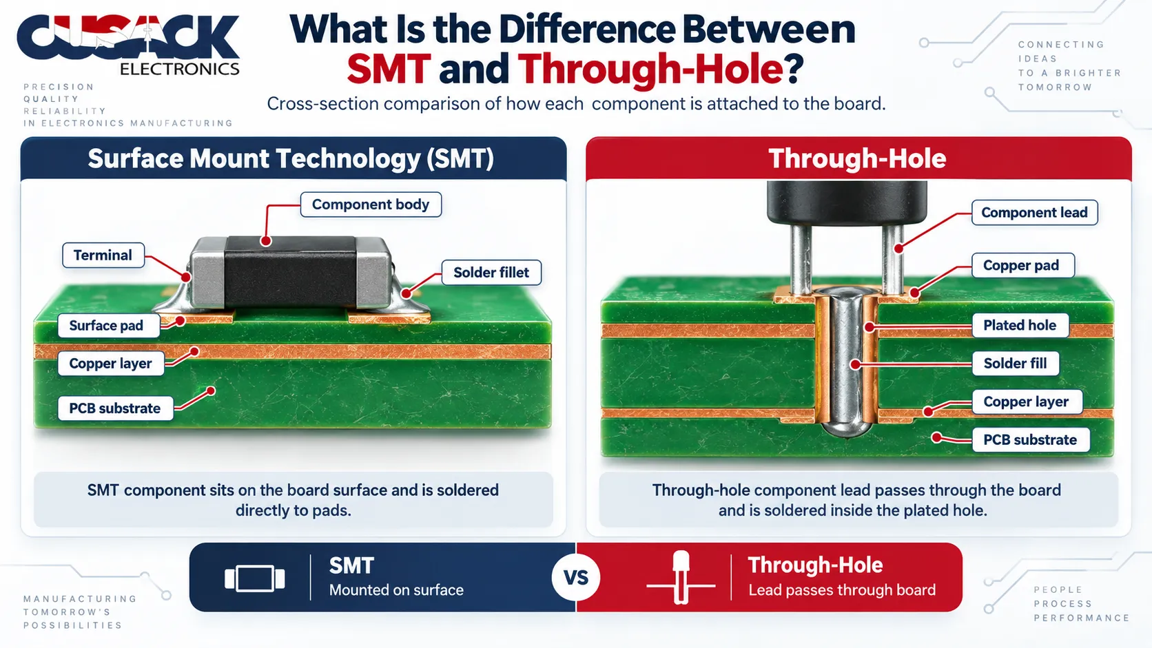
The difference between SMT and through-hole is how each part connects to the board. Surface-mount technology (SMT) solders components directly onto copper pads on the board surface. Through-hole technology (THT) inserts component leads through plated holes drilled in the board and solders them on the opposite side.
Think about hanging something on a wall. An adhesive hook goes up fast, needs no hole, and holds a light frame perfectly well. A toggle bolt needs a drilled hole and takes longer, but it will hold a heavy shelf that gets pulled on every day.
SMT is the adhesive hook. Through-hole is the toggle bolt. Every printed circuit board assembly (PCBA) is built with one of them, and usually both.
Neither is better in general. Each is better for a particular kind of load.
What Does SMT Stand For?
SMT stands for surface-mount technology, also written surface-mount technology. It was originally called planar mounting, and parts built for it are called surface-mount devices (SMDs): the SMD is the part, and SMT is the method.
The approach is older than most people assume. According to Wikipedia’s account of surface-mount technology, IBM did pioneering work in the 1960s, and the technique later went into guidance computers for the Saturn launch vehicles.
Adoption was slow at first. By 1986, surface-mounted components made up at most 10% of the market. By the late 1990s, they dominated most high-tech circuit assemblies.
What Is Through-Hole Technology?
Through-hole technology is the original way of building circuit boards. A through-hole component has wire leads that pass through holes in the board, and the holes are plated with copper so the solder joint forms inside the hole and on the far side.
Through-hole components come in a few familiar shapes: axial parts with a lead out each end, radial parts with both leads out the bottom, and dual in-line packages with two rows of pins. Their joints are made by wave soldering, selective soldering, or by hand.
SMT vs Through-Hole Technology: How Do They Compare Side by Side?
SMT vs through-hole technology differs in almost every attribute that matters in design and manufacturing. The table covers the ones that change real decisions.
| SMT (surface mount) | Through-hole (THT) | |
|---|---|---|
| How parts attach | Soldered to pads on the surface | Leads pass through plated holes |
| Holes needed | Few (vias only) | One per lead |
| Component size | Very small, down to near grain-of-sand scale | Larger, with long leads |
| Density | High, and both board sides usable | Lower, leads block the far side |
| Main soldering method | Reflow soldering | Wave, selective, or hand soldering |
| Automation | Fully automated, by pick-and-place machine | Insertion often partly manual |
| Pull-out and shear strength | Lower | Higher |
| Behavior under vibration | Good, because parts are light | Heavy parts on long leads can flex and fatigue |
| High-frequency performance | Better, shorter leads | Worse, longer leads add inductance |
| Hand soldering and rework | Hard for fine-pitch parts | Easy |
| Typical parts | ICs, resistors, capacitors, most modern parts | Connectors, switches, transformers, large capacitors |
Two rows matter more than the rest: pull-out strength and vibration. They point in opposite directions, and that is where most bad decisions start.
How Does SMT vs Through-Hole Assembly Work?
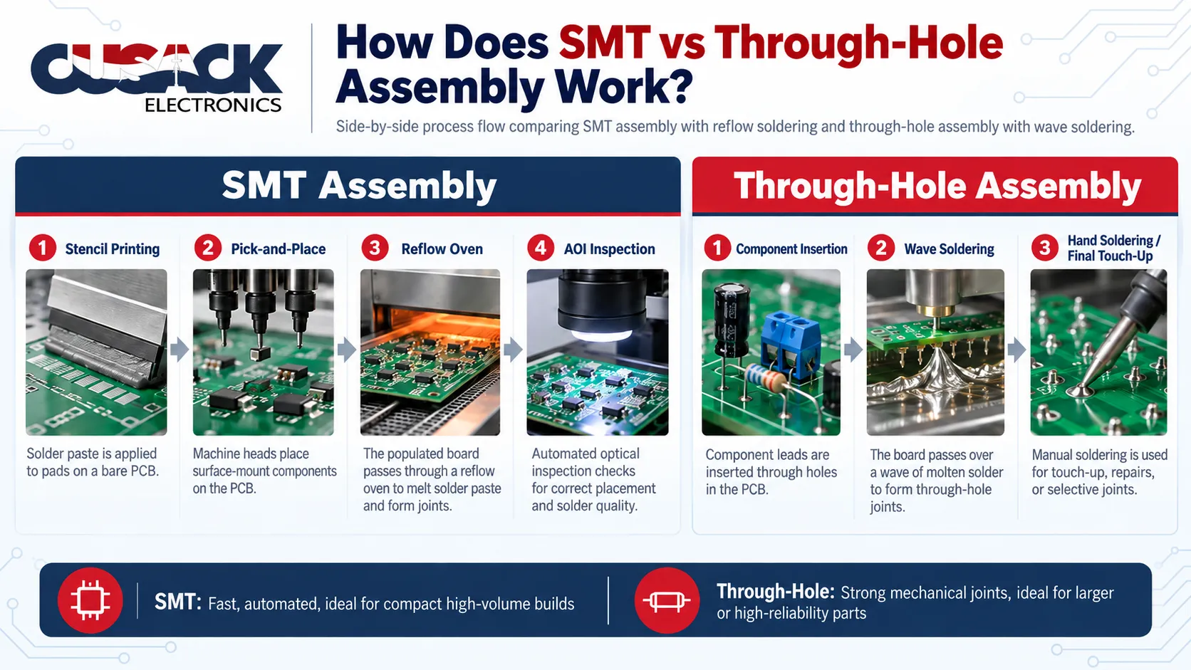
SMT vs. through-hole assembly runs on two different production flows, and the difference in flow is what drives most of the cost gap.
SMT assembly is a single automated line:
- Solder paste is printed onto every pad through a stencil
- A pick-and-place machine sets each surface-mount device onto its pads
- Reflow soldering melts the paste in a temperature-controlled oven, forming every joint at once
- Automated optical inspection (AOI) checks position and joints with cameras
Placement speed is where SMT pulls ahead. Wikipedia notes that placement machines can exceed 136,000 components per hour.
Through-hole assembly is slower and often partly manual:
- Insertion pushes leads through the holes, by machine for common parts or by hand for odd shapes
- Wave soldering passes the underside of the board over a standing wave of molten solder, soldering every exposed lead in one pass
- Selective soldering uses a small targeted fountain of solder when only some joints need it
- Hand soldering covers anything left over, plus rework
Wave soldering is the through-hole equivalent of reflow: one pass, many joints. It has limits, though, which matter as soon as a board carries both kinds of parts. The full line, stage by stage, is in my complete guide to PCB assembly.
Is Through-Hole Really More Reliable Than SMT?
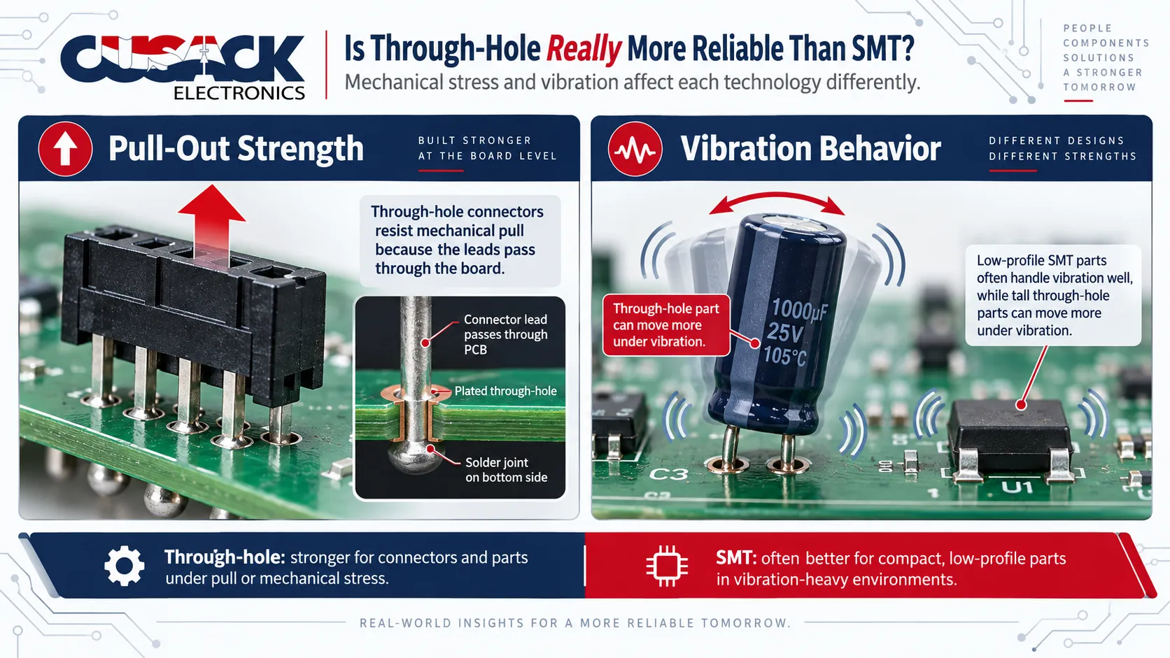
Through-hole is more reliable against pulling and prying forces, but not automatically against vibration. The flat claim that through-hole is the rugged choice is half right, and the wrong half causes real design mistakes.
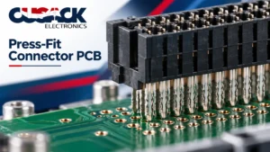
Here is where through-hole genuinely wins. A lead passing through the board and soldered on both sides resists being pulled out or sheared off far better than a pad joint. That is why a USB port, a terminal block, or a power jack that gets plugged in hundreds of times usually goes through the board.
Heavy parts are the other clear case. A large transformer or a big electrolytic capacitor has enough mass that a surface joint alone would be carrying all of it.
Vibration is a different story. A heavy part on long leads behaves like a weight on a spring: shake the board and it swings, flexing the joints every cycle. A tiny surface-mount device has almost no mass to swing. Wikipedia lists better mechanical performance under shock and vibration as an SMT advantage, not a weakness.
The market has noticed. Mordor Intelligence’s July 2026 report on the US electronics manufacturing services market says through-hole technology endures in power-conversion modules and avionics, but its share keeps slipping as vibration-resistant SMT packages spread into military and aerospace catalogs.
Even NASA treats this as one discipline now. It once published a dedicated surface mount workmanship standard, NASA-STD-8739.2, alongside a separate soldering standard. Both are cancelled.
Its current workmanship rulebook, in force since 2021, names one soldering standard for its mission hardware: IPC J-STD-001 with its space and military addendum.
That rulebook is NASA-STD-8739.6B, and it no longer treats surface mount as a separate craft.
My working rule is simple. Put a part through the board if it will be pulled, pushed, or is heavy enough to matter. Otherwise, surface mount it.
Which Is Cheaper, SMT or Through-Hole?
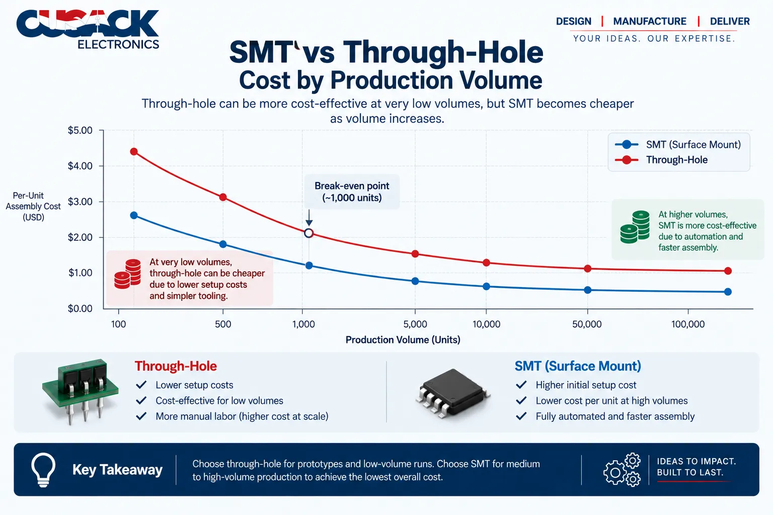
SMT is cheaper for almost every board built in any real volume, because automation spreads the setup cost and every joint is formed in one reflow pass. Through-hole can be cheaper for a handful of prototypes, because it needs no stencil and can be soldered by hand.
The volume shift shows up in the data.
Surface-mount technology took 72.99% of US electronics manufacturing services process revenue in 2025, according to Mordor Intelligence.
The hidden cost is not either method. It is running both. Picture a board with 200 surface mount components and three through-hole connectors. Those three connectors can require a whole second soldering process, with its own setup, fixtures, and inspection.
A few other cost drivers are easy to miss:
- Drilling: every through-hole lead needs a plated hole, which adds fabrication time
- Board area: through-hole parts are larger, so the board may need to grow
- Manual labor: odd-shaped through-hole parts are often inserted by hand, while a pick-and-place machine handles SMT parts without an operator touching them
- Rework: through-hole is cheaper to repair; fine-pitch SMT needs specialist tools
For the full quote mechanics, see my breakdown of what drives PCB assembly cost.
Why Do Most Boards Use Mixed Assembly?
Mixed assembly means building one printed circuit board assembly with both SMT and through-hole components. It is the norm rather than the exception, because almost every product needs at least one part that should not sit on a surface pad.
Wikipedia puts it plainly: through-hole is often used on SMT boards for parts not suited to surface mounting, such as large transformers and heat-sinked power semiconductors.
The usual build order is SMT first, then through-hole:
- Print paste, place parts, and reflow the surface mount side
- Insert the through-hole components
- Solder them by wave, by selective soldering, or by hand
- Inspect both kinds of joint
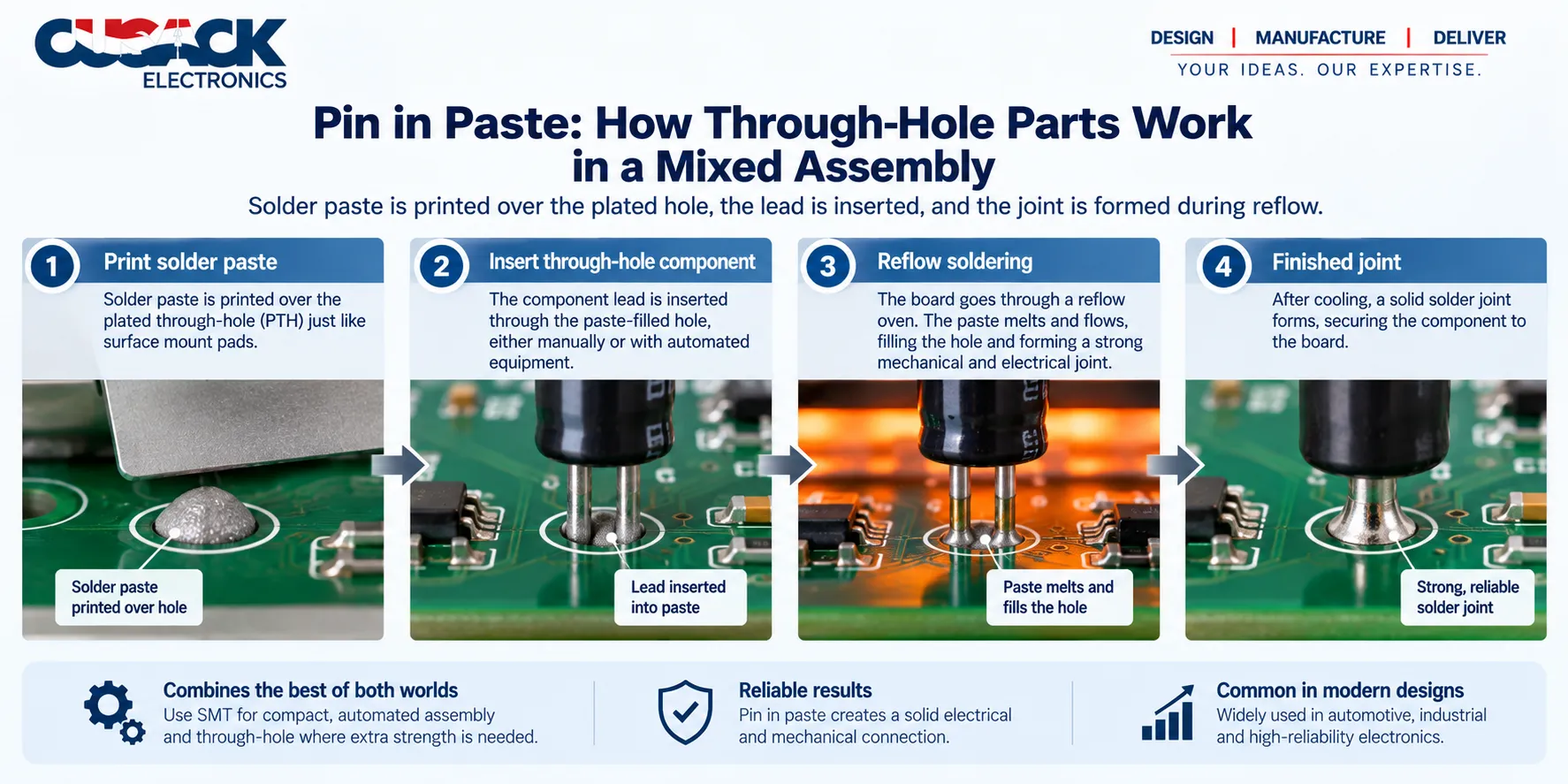
There is a smarter option for boards with only a few through-hole parts. Pin-in-paste, also called through-hole reflow, prints solder paste into and around the holes, inserts the leads, and reflows everything in the same oven pass as the SMT parts. The second soldering process disappears.
The catch: the through-hole part has to survive reflow temperatures, and many connectors and electrolytic capacitors are not rated for it. Check the datasheet before you design around pin-in-paste.
Selective soldering covers the remaining cases. Wave soldering floods the whole underside of the board, which is a problem if surface mount parts already sit there. A selective fountain solders only the through-hole joints and leaves the rest alone.
What Changes in Layout When a Board Mixes Both?
A mixed board costs less to build when its layout respects both processes. A few rules make the biggest difference:
- Keep through-hole parts on one side: one insertion pass and one soldering pass then reach every joint
- Leave keep-out space around through-hole pins: a selective solder nozzle needs clearance from nearby surface mount parts
- Keep bottom-side surface mount parts small and low: tall parts shadow the wave and leave joints unsoldered
- Use thermal relief on through-hole pads tied to large copper areas: otherwise the plane pulls heat away and the hole never fills
None of these rules is exotic, but each one skipped tends to add a manual step. They are exactly the kind of issue a design for manufacturability review is meant to catch before the board is fabricated.
How Do SMT and Through-Hole Handle Heat and Power?
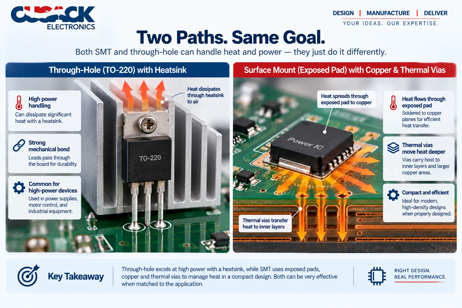
Through-hole and surface mount parts move heat out through different paths, and that often decides the package for power components.
A through-hole power part, such as a transistor in a TO-220 package, carries heat two ways: down its leads into the board, and out through a metal tab that bolts onto a heatsink.
The heatsink hangs off the part and does most of the work. That arrangement is simple and forgiving, which is why it survives in power supplies and motor drives.
A surface mount power part pushes heat down into the board instead. Many have an exposed metal pad on the underside, soldered to a copper area, with thermal vias (small plated holes) carrying heat to inner layers or the far side. The board itself becomes the heatsink.
Think of it as the difference between a radiator bolted onto a wall and underfloor heating. Both move the heat, but the second one only works if the floor was designed for it from the start.
That is the practical point. Surface mount power parts can match through-hole ones, but only when the copper layout is planned around them. Swapping a through-hole regulator for a surface mount one late in a design, without room for copper, is how boards end up running hot.
SMT or Through-Hole: Which Should You Choose?
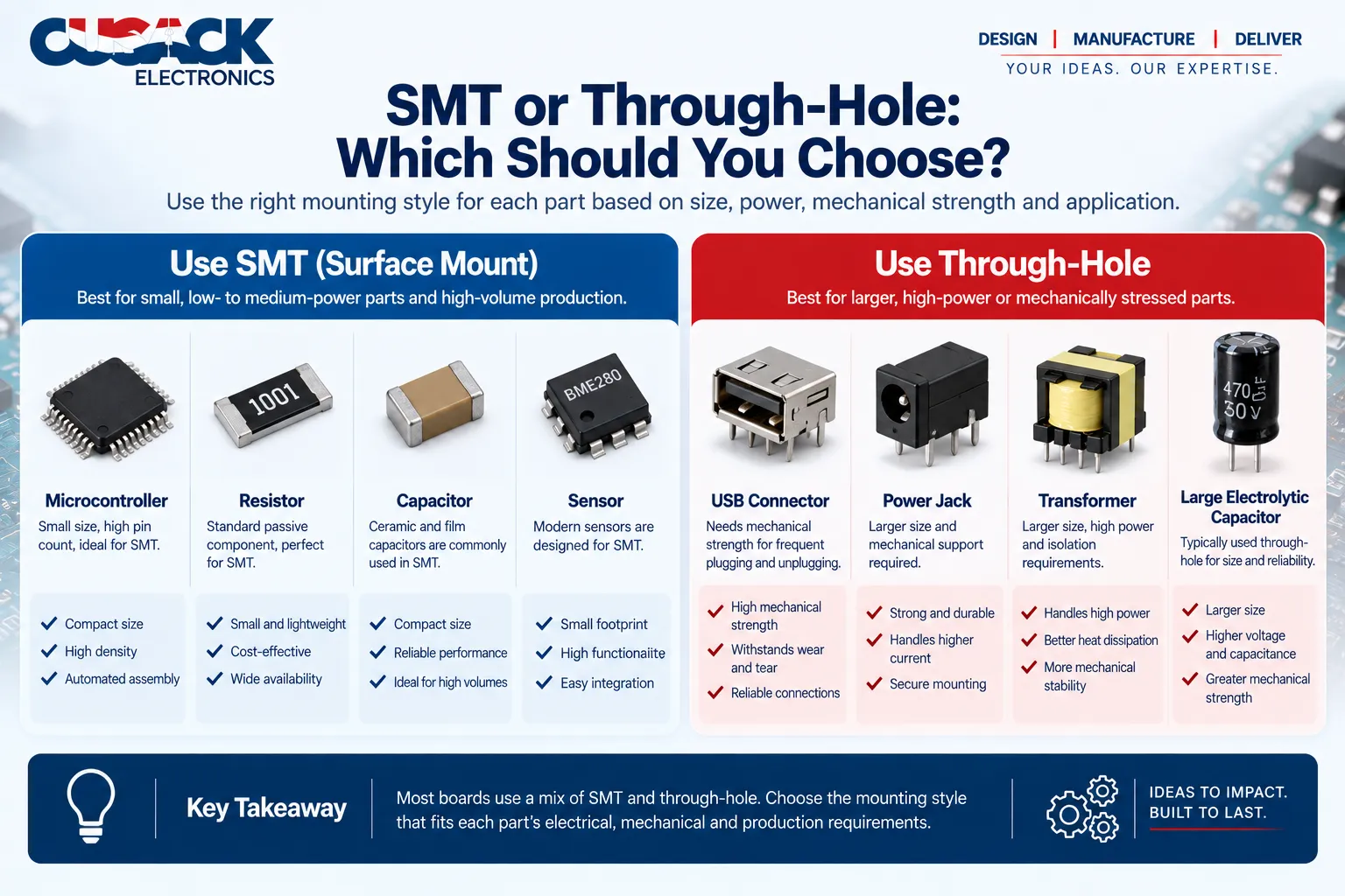
Surface mount vs through hole is rarely an either-or decision for a whole board. Make it part by part.
Choose SMT when:
- Size matters: SMT parts are far smaller, and both sides of the board are usable
- You are building in volume: automated placement and reflow bring the unit cost down fast
- Signals are fast: shorter leads mean less parasitic inductance and better high-frequency behavior
- The part is light and carries no mechanical load: most ICs, resistors, and capacitors
Choose through-hole when:
- The part takes force: connectors, jacks, switches, and anything plugged or pressed repeatedly
- The part is heavy or hot: transformers, large capacitors, and heat-sinked power devices
- You are hand-building or prototyping: through-hole fits breadboards, sockets, and a basic iron
- Only a through-hole package exists: some high-power and legacy parts come no other way
Honest caveat: the choice is sometimes made for you. Component availability can override every rule above, so check what packages your key parts actually come in before you lay out the board. My guide to PCB layout design covers footprint choices in more depth.
The Bottom Line
SMT is the default for modern electronics: smaller, faster to build, cheaper at volume, and better than its reputation under vibration. Through-hole earns its place wherever a part is pulled, pushed, heavy, or hot.
Most boards need both, so design the mix on purpose. Keep through-hole parts to the few that genuinely need it, and consider pin-in-paste so those few do not force a second soldering process.
Working on a board that mixes both? Send me your design files and I will come back with a quote and a straight read on which parts belong through the board. Request a quote here.
Frequently Asked Questions
Is through-hole technology obsolete?
No. Through-hole is shrinking as a share of assembly, but it remains the standard choice for connectors, high-current parts, transformers, and anything that takes repeated mechanical force. Many products that look fully surface mount still carry a few through-hole connectors. It has become a specialist method rather than a default one.
Can you hand-solder SMT components?
Yes, for larger packages. Surface mount resistors and capacitors in the bigger sizes, and chips with widely spaced leads, can be soldered with a fine-tipped iron, flux, and patience. Fine-pitch chips and ball grid arrays are a different matter, because their joints are too small or sit hidden beneath the package.
What is wave soldering?
Wave soldering is a through-hole process where the underside of an assembled board passes over a pumped, standing wave of molten solder. The solder wets every exposed lead and plated hole in a single pass. It is fast and consistent for through-hole joints, but it can disturb surface mount parts already fixed to the underside.
How are SMT and through-hole joints inspected?
SMT boards go through automated optical inspection, where cameras compare every part and joint against the expected image. Hidden joints, such as those under ball grid arrays, need X-ray inspection. Through-hole joints are checked for solder fill inside the hole and a proper fillet on each side, visually or with AOI after wave soldering.
The wider toolkit is in my guide to PCB testing and inspection methods.
Is surface mount better for high-frequency circuits?
Generally, yes. Surface mount parts have much shorter leads, and shorter leads add less parasitic inductance and capacitance. That keeps fast signals cleaner and reduces electromagnetic interference. This is one reason radio frequency and high-speed digital designs lean heavily on SMT, even when through-hole versions of the same parts exist.
Can a through-hole part be swapped for an SMT equivalent?
Often, but it is not a drop-in change. The board footprint has to be redesigned, and the surface mount version may have a different current rating, power dissipation, or thermal behavior. For connectors and parts under mechanical load, check whether the surface mount version has anchoring features before you switch.