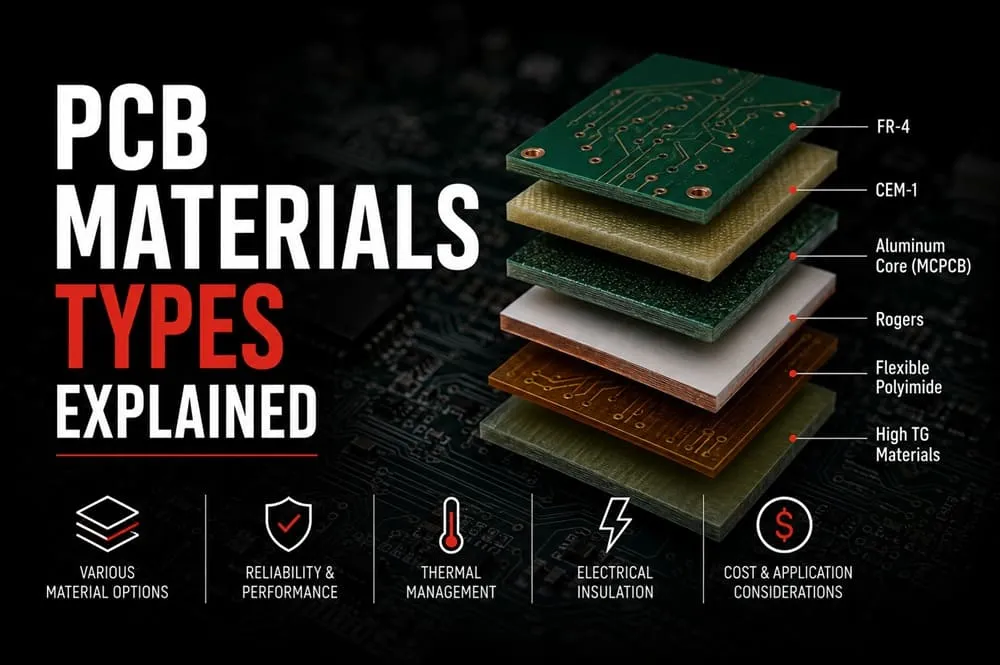
Every PCB looks similar from the outside — a green (or blue, or black) board with copper traces and mounted components. But underneath that surface, the specific PCB materials used determine how well that board performs, how much heat it can handle, how it flexes, and how long it lasts in the field. Choosing the wrong material for the application is one of the most common — and most expensive — design mistakes.
This guide breaks down the different PCB material options, starting with how a board is actually built, layer by layer.
Anatomy of a PCB: Where Materials Matter
A typical rigid PCB is built from several layers, each using different materials suited to its function:
- Substrate (core material) — the rigid base layer that gives the board its structure
- Copper foil — thin conductive layers that form the electrical traces
- Prepreg — resin-impregnated layers that bond multiple copper/substrate layers together in multilayer boards
- Solder mask — the colored protective coating that prevents solder bridging and oxidation
- Silkscreen — the printed labeling layer identifying components and test points
Of these, the PCB substrate material has the biggest impact on the board’s mechanical strength, thermal performance, and electrical characteristics — which is why it’s usually the first decision made during material selection.
FR4: The Industry-Standard PCB Substrate
The most common PCB FR4 material is a glass-reinforced epoxy laminate, and it’s the default substrate for the vast majority of PCBs produced today. FR4 earned this position because it offers a solid balance of:
- Good mechanical strength and rigidity
- Reliable electrical insulation properties
- Reasonable cost at virtually any production volume
- Wide availability across manufacturers worldwide
For general-purpose electronics — consumer devices, industrial controls, and most everyday circuit boards — FR4 remains the default choice unless a specific requirement pushes the design toward an alternative material.
Types of PCB Materials Beyond FR4
While FR4 covers most applications, several other types of PCB materials exist for situations where FR4 falls short:
| Material | Key Property | Common Use Case |
| FR4 | Balanced cost, strength, and insulation | General-purpose electronics |
| CEM-1 / CEM-3 | Lower cost, less rigid than FR4 | Simple, single-layer, cost-sensitive boards |
| Polyimide | Flexible, high heat resistance | Flexible and rigid-flex PCBs |
| PTFE (Teflon-based) | Very low signal loss at high frequencies | RF and microwave circuits |
| Aluminum-backed (Metal Core) | Excellent heat dissipation | High-power LED and power electronics boards |
| Ceramic | Extremely high thermal conductivity | High-power, high-reliability applications |
PCB Laminate Materials for Multilayer Boards
For boards with more than two layers, PCB laminate materials — the resin systems bonding copper and substrate layers together — become just as important as the base substrate itself. Standard FR4 laminates work well for most multilayer boards, but higher-frequency or higher-temperature applications often require specialized laminate formulations designed to reduce signal loss and withstand repeated thermal cycling during assembly and operation.
High Frequency PCB Materials
Standard FR4 starts to lose signal integrity at higher frequencies, which is why high frequency PCB materials — typically PTFE-based laminates — are used for RF, microwave, and high-speed digital designs. These specialized materials offer:
- Lower dielectric loss, preserving signal strength over distance
- More stable electrical properties across varying frequencies and temperatures
- Better performance in applications like wireless communication, radar, and high-speed data transmission
The tradeoff is cost — high frequency PCB materials are significantly more expensive than standard FR4, so they’re typically reserved for applications where signal performance genuinely requires it.
Flexible PCB Material
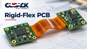
Not every board is rigid. Flexible PCB material — most commonly polyimide — allows a circuit to bend, fold, or flex repeatedly without cracking, making it ideal for applications with tight space constraints or moving parts. Flexible and rigid-flex designs are increasingly common in compact consumer electronics, wearables, and any product where a traditional rigid board simply doesn’t fit the available space.
Choosing between rigid, flexible, or rigid-flex construction typically depends on the product’s mechanical requirements and should be decided early in the design process — ideally alongside your PCB assembly partner, since material choice affects manufacturability and assembly process.
How to Choose the Right PCB Material
Selecting the right PCB materials for your project comes down to a few key questions:
- What’s the operating environment? High heat or power dissipation needs point toward metal-core or ceramic substrates.
- What frequencies is the circuit operating at? High-speed or RF designs may require specialized high frequency PCB materials.
- Does the design need to flex or fit into a tight space? Flexible or rigid-flex construction may be necessary.
- What’s the budget and production volume? FR4 remains the most cost-effective option for the vast majority of standard applications.
Getting this decision right early avoids costly redesigns later, since switching substrate materials after a board layout is finalized often requires significant rework.
Board Thickness and Copper Weight Considerations
Material selection isn’t limited to substrate type alone. Two related specifications also affect how a PCB material performs in practice:
- Board thickness — standard boards typically run 0.8mm to 1.6mm, with thicker boards offering more mechanical rigidity and thinner boards suited to compact or flexible designs
- Copper weight — measured in ounces per square foot, heavier copper weights support higher current capacity but add cost and can affect trace spacing requirements
Both specifications should be decided alongside substrate material selection, since they interact directly with the board’s thermal and electrical performance. A high-power design using metal-core substrate, for example, often pairs with heavier copper weight to handle higher current loads effectively.
Final Thoughts
PCB materials aren’t a one-size-fits-all decision — the right substrate, laminate, and construction type depend entirely on your product’s electrical, thermal, and mechanical requirements. While FR4 remains the reliable default for most designs, understanding the alternatives ensures you’re not forcing a standard material into an application it wasn’t built for.
If you’re unsure which PCB material fits your next project, reach out to our team to talk through your design requirements.