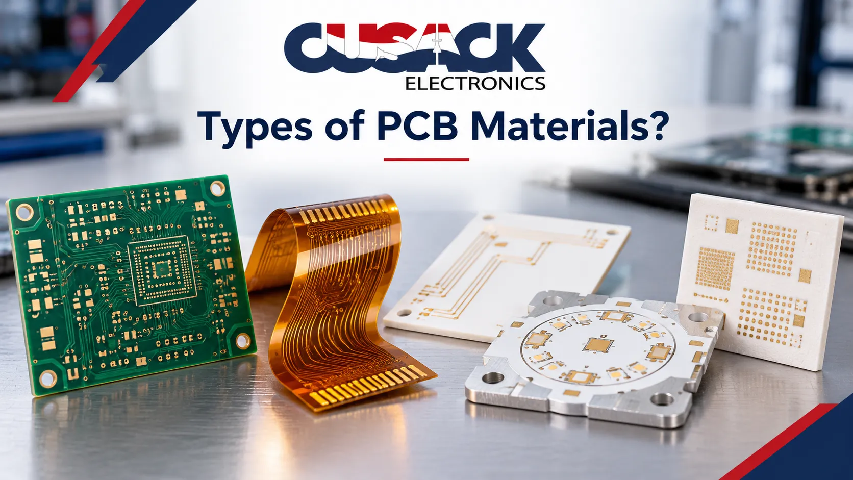
What you need to know about the types of PCB materials
- Default to FR4. It covers most boards on cost, strength and insulation, and it is the best material for printed circuit boards when nothing unusual is asked of them.
- Switch only for a reason you can name: heat (metal core or ceramic), frequency (PTFE or Rogers), or bending (polyimide).
- Read the datasheet numbers: Tg, Td, Dk, Df and CTE predict most material failures.
- Lead-free reflow peaks near 260 C, so Td matters as much as Tg.
- Laminate prices moved in 2026. Lock your material early and ask for quote validity dates.
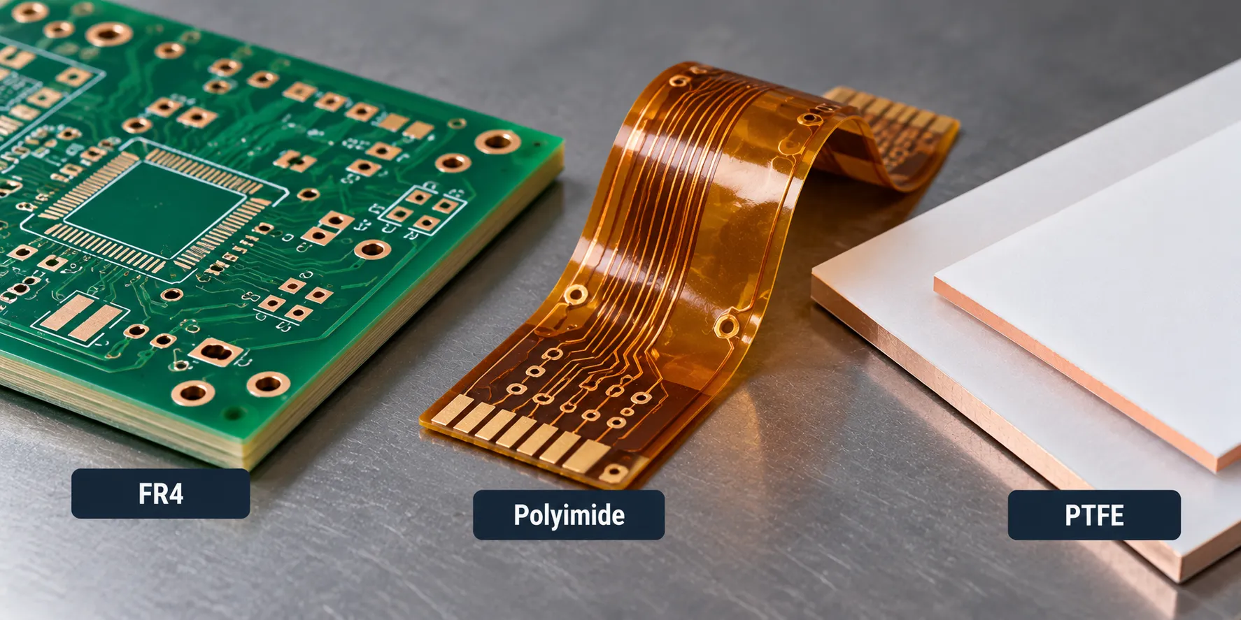
The main types of PCB materials are FR4, CEM-1 and CEM-3, polyimide, PTFE, metal core and ceramic. Each one decides how a board handles heat, signals and bending over its whole life. Picking the wrong one is a common and expensive design mistake, and it usually shows up after layout, when a change means rework.
What are PCBs made of, and where do PCB materials matter?
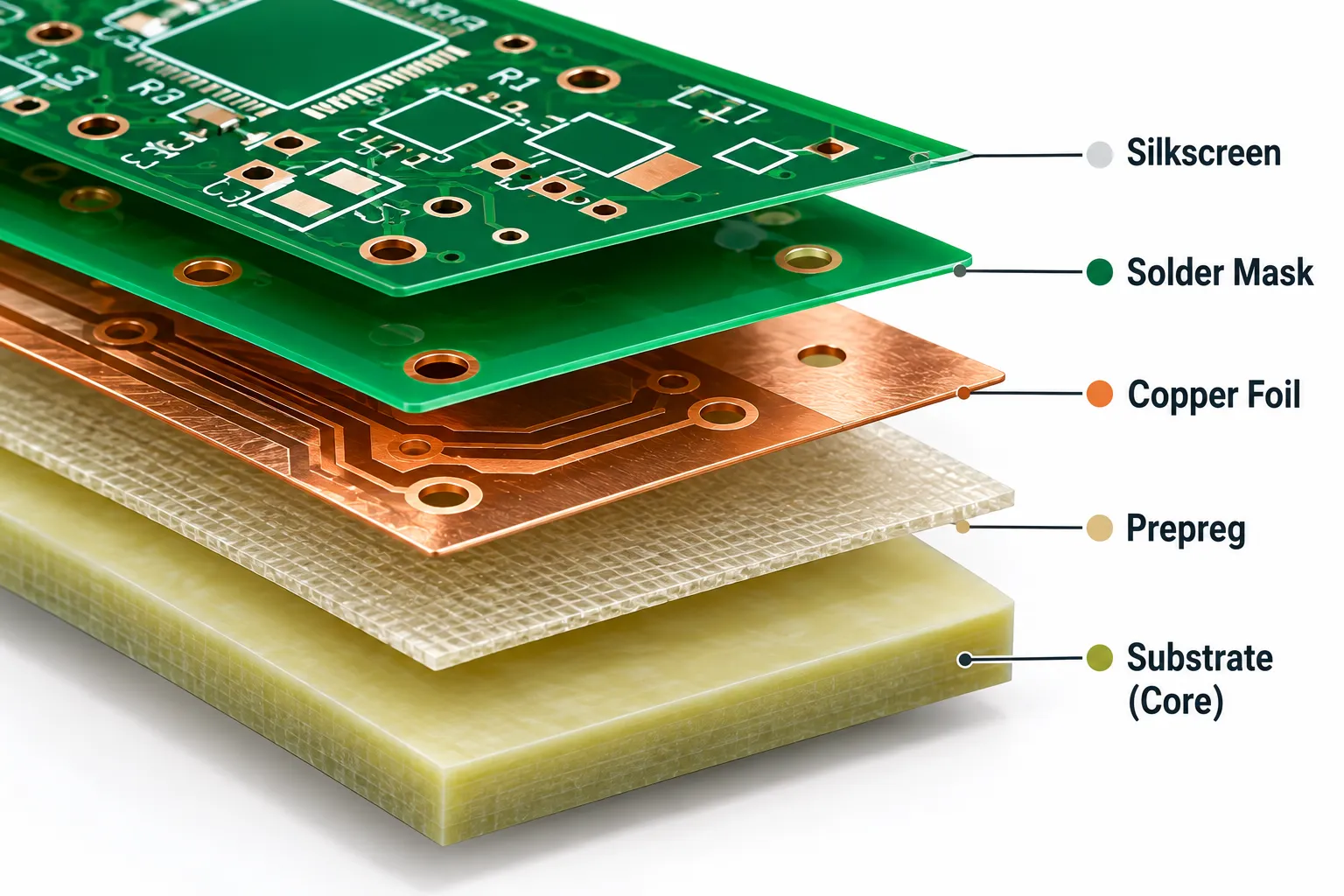
A rigid PCB is a stack of five material layers, and the substrate has the biggest effect on strength, heat and electrical behavior. Think of the board as a sandwich: the substrate is the bread, and everything else sits on or between it.
- Substrate (core): the rigid base that gives the board its structure, built from epoxy resin reinforced with fiberglass in the most common case.
- Copper foil: the conductive layers that form traces.
- Prepreg: resin-impregnated glass that bonds copper and core layers in multilayer boards.
- Solder mask: the colored coating that stops solder bridging and protects against oxidation.
- Silkscreen: the printed labels for components and test points.
Suppliers sell the core and copper together as copper-clad laminate (CCL), which is why PCB base materials and printed circuit board materials are often discussed as laminates. The substrate is usually the first material decision. Our PCB assembly guide shows how that choice carries into the build.
Why is FR4 the default PCB material?
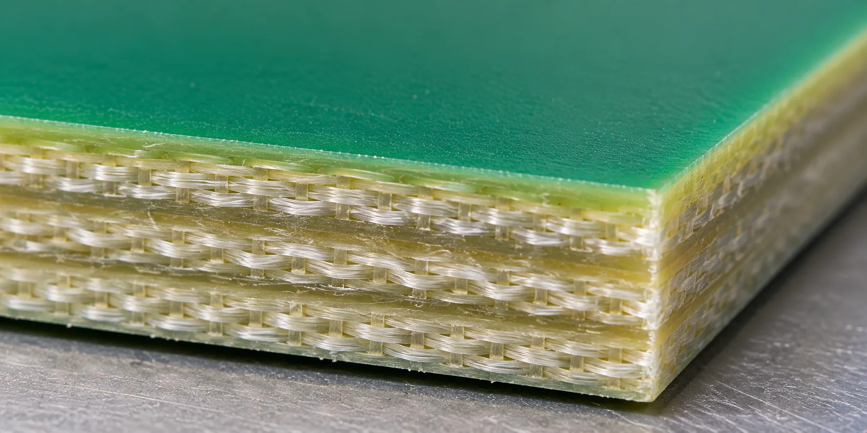
FR4 (also written FR-4) is a glass-reinforced epoxy laminate, and it is the default among PCB substrate materials because it balances strength, insulation and cost better than anything else at volume. The “FR” stands for flame retardant.
FR4 gives you rigidity, reliable insulation, a reasonable price at any quantity and wide global supply. It stays the right answer for consumer devices, industrial controls and most everyday boards. Our opinion: start with FR4 PCB material, and leave it only when a datasheet number forces you to.
What are the types of PCB materials beyond FR4?
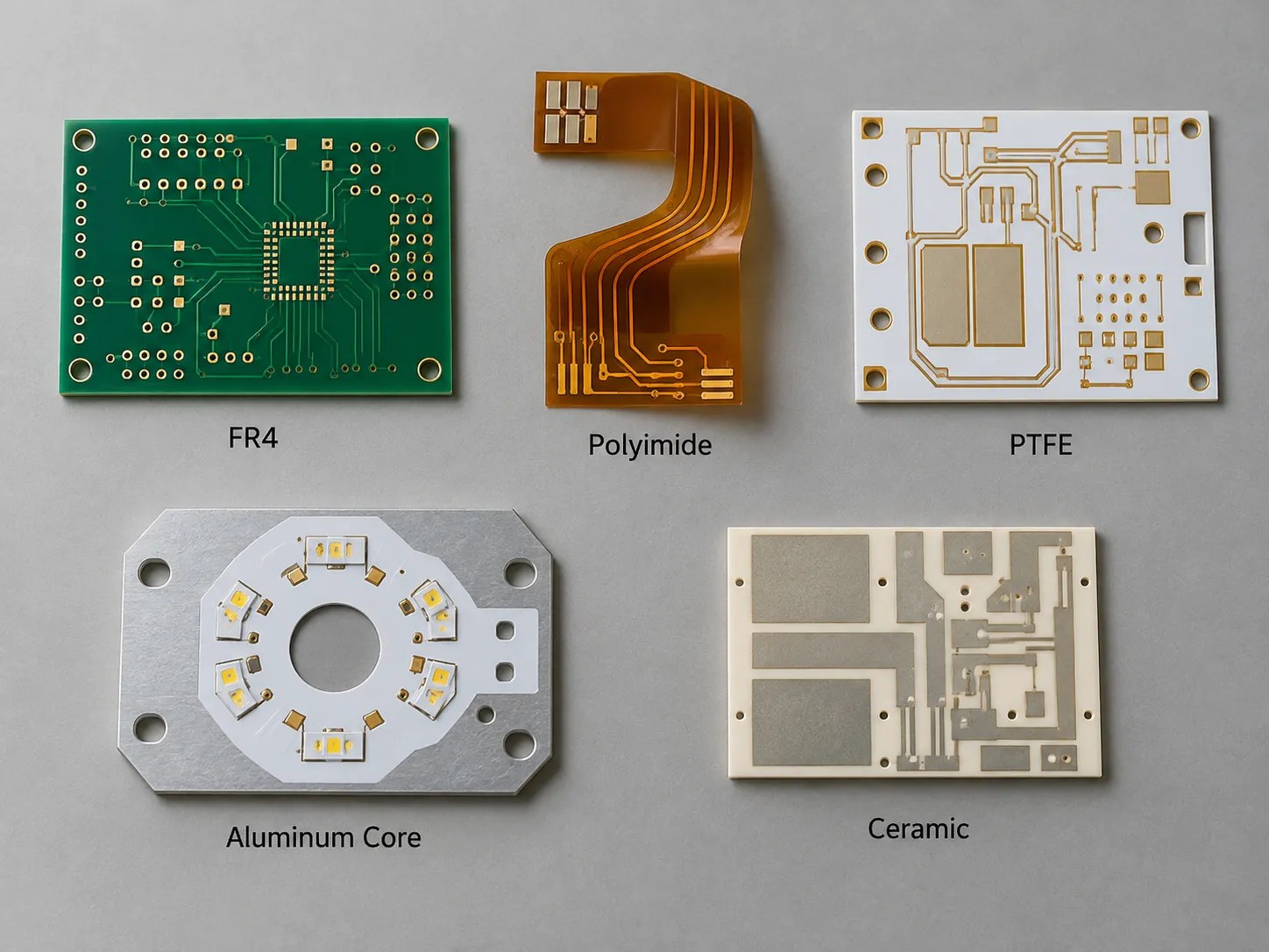
The main types of PCB substrates beyond FR4 are FR-2, CEM-1 and CEM-3, BT resin, polyimide, PTFE, metal core and ceramic, and each one fixes a specific problem FR4 cannot. These circuit board material types are listed below with what each is and where it fits.
| Material | Key property | Best for |
|---|---|---|
| FR4 | Balanced cost, strength and insulation | General-purpose electronics |
| FR-2 | Paper-based, lowest cost | Simple single-sided consumer boards |
| CEM-1 / CEM-3 | Lower cost, less rigid than FR4 | Simple, single-layer, cost-sensitive boards |
| BT resin | Stable at heat, good electrical behavior | Demanding, high-reliability boards |
| Polyimide | Flexible, high heat resistance | Flexible and rigid-flex PCBs |
| PTFE (Teflon-based) | Very low signal loss at high frequency | RF and microwave circuits |
| Aluminum PCB or copper core (MCPCB) | Excellent heat dissipation | High-power LED and power boards |
| Ceramic substrates | Very high thermal conductivity | High-power, high-reliability designs |
How do PCB materials compare side by side?
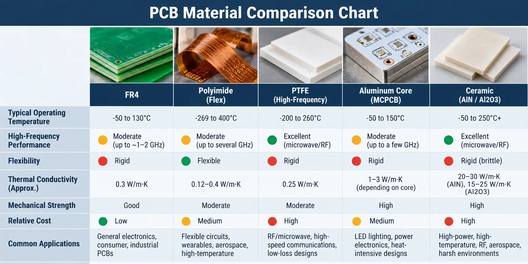
Use this comparison chart to shortlist two or three PCB materials, then confirm against datasheets. The ratings are our rule of thumb, not measured values, and real laminates vary by grade.
| Material | Heat handling | High frequency | Flexibility | Relative cost |
|---|---|---|---|---|
| FR-2 | Low | Poor | Rigid | Lowest |
| CEM-1 / CEM-3 | Low to moderate | Poor | Rigid | Low |
| FR4 | Moderate, better in high-Tg grades | Fair | Rigid | Low |
| BT resin | High | Good | Rigid | Medium to high |
| Polyimide | High | Fair | Flexible | Medium to high |
| PTFE / Rogers | Moderate to high | Excellent | Rigid | High |
| Aluminum or copper core | Excellent heat spreading | Poor | Rigid | Medium |
| Ceramic | Excellent | Good | Rigid and brittle | High |
If two rows both fit, pick the cheaper one. The comparison of PCB materials only matters where the product truly needs the extra performance.
Which PCB material properties matter: Tg, Td, Dk, Df and CTE?
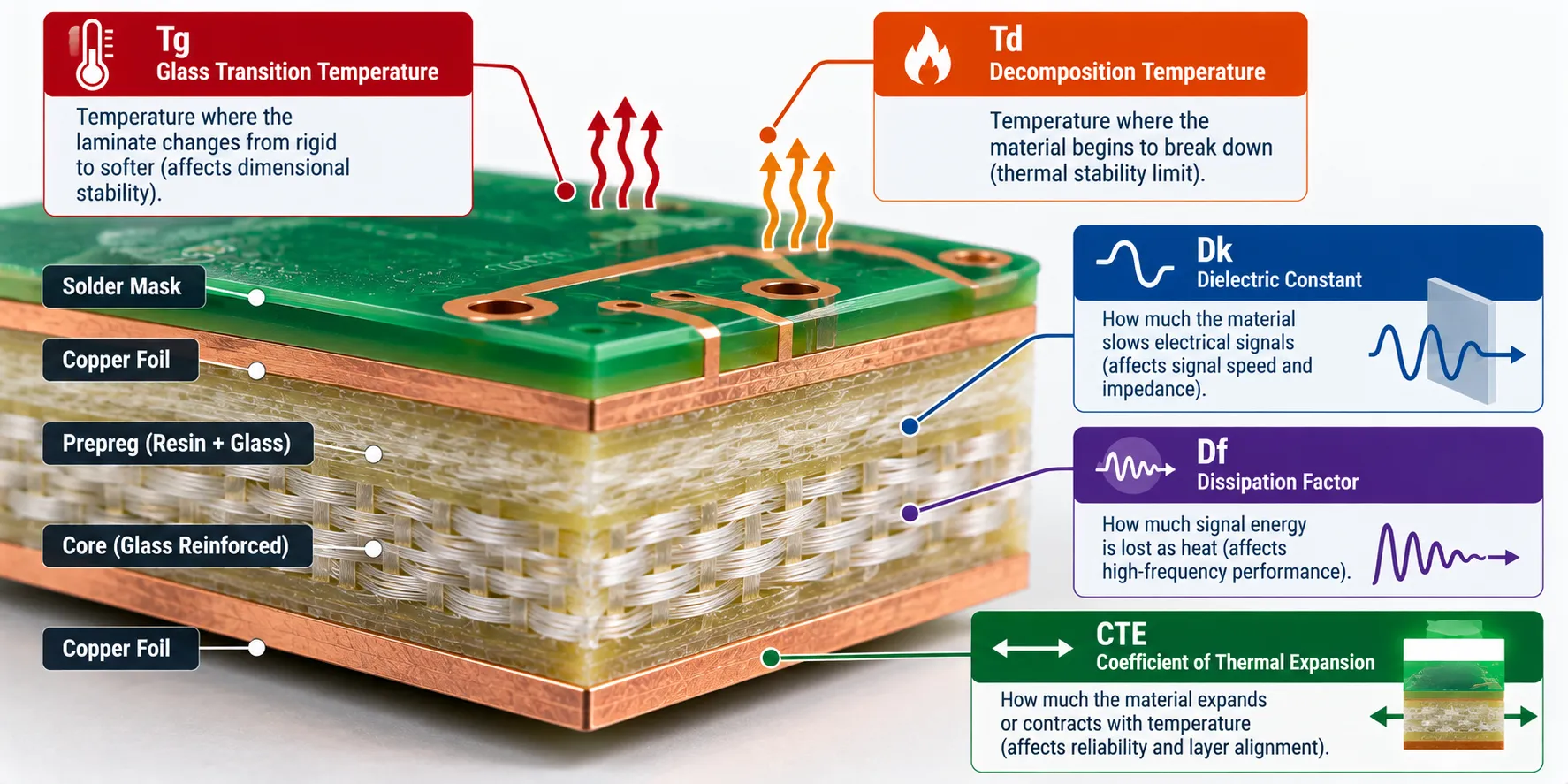
Seven numbers on a laminate datasheet predict most problems: Tg, Td, Dk, Df, CTE, thermal conductivity and dielectric strength. Here is what each one tells you, with a plain comparison.
- Tg (glass transition temperature): where the resin turns from stiff to rubbery, like a hard candy going soft in a hot car. High-Tg FR4 grades hold their shape at higher temperatures.
- Td (decomposition temperature): where the resin starts to break down for good. Past Td, damage is permanent.
- Dk (dielectric constant): how much the material slows a signal. Lower and steadier is better for fast circuits and signal integrity.
- Df (dissipation factor): how much signal energy turns into heat. Think of it as friction on a signal.
- CTE (coefficient of thermal expansion): how much the board grows when hot. A mismatch with copper stresses plated holes.
- Thermal conductivity: how well the material carries heat away. It is the reason metal core and ceramic exist, and a low thermal resistance path keeps parts cooler.
- Dielectric strength: how much voltage the insulation survives before it breaks down.
One caveat: FR4 is a family, not one material. Its Dk and Tg change with resin content and glass style, so read the datasheet for the exact laminate you plan to use.
How do PCB types change the material choice?
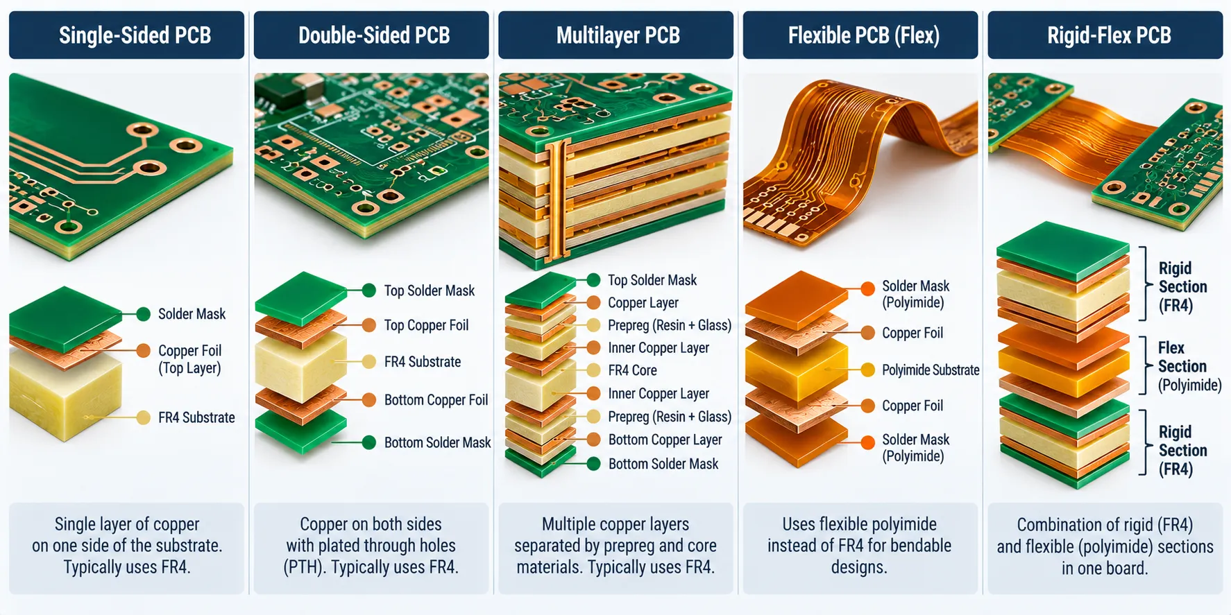
The board type narrows the material choice before you look at a datasheet. Single-sided and double-sided boards are the simplest and can use low-cost CEM or FR4. A multilayer PCB adds prepreg and puts more weight on Tg, Td and CTE.
Flexible boards need polyimide, and a rigid-flex PCB combines polyimide with rigid FR4 sections in one assembly. Rigid boards use the full range of rigid PCB materials. Decide the board type first, because it removes half the options.
Which PCB laminate materials suit multilayer boards?
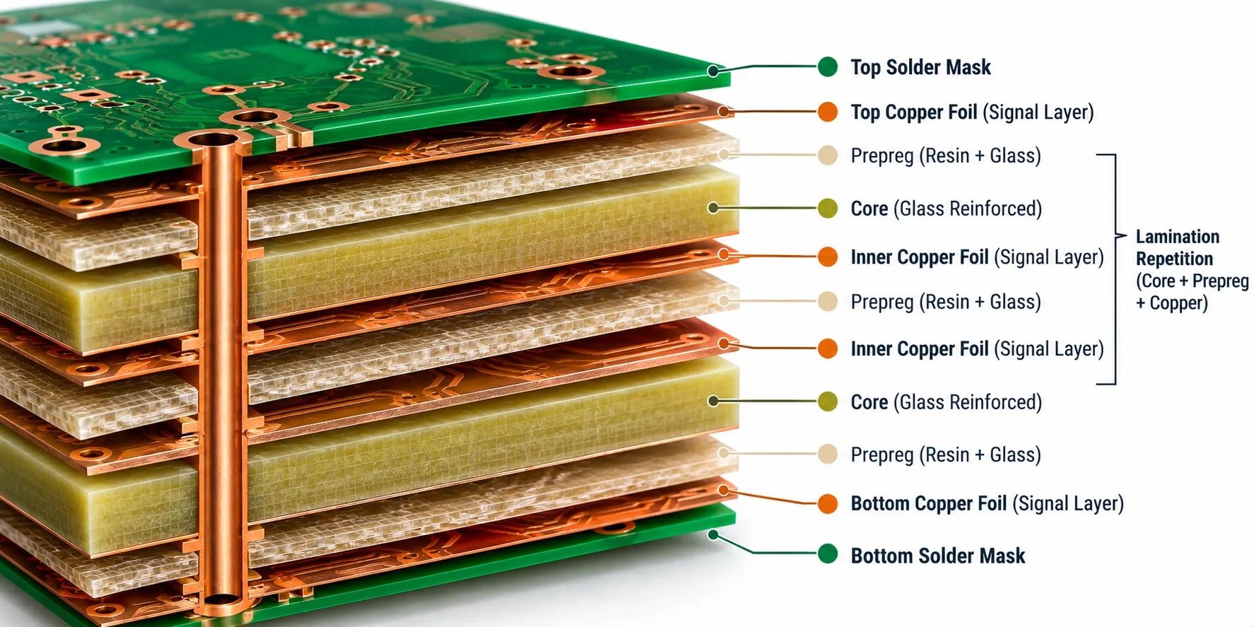
On a board with more than two layers, the laminate resin system that bonds the copper matters as much as the substrate. Standard FR4 laminates suit most multilayer designs.
Designs that run hot or fast often need specialized PCB laminate materials. These cut signal loss and survive repeated thermal cycling during assembly and in the field. For dense boards, see our post on HDI PCB types.
Will your PCB material survive lead-free assembly?
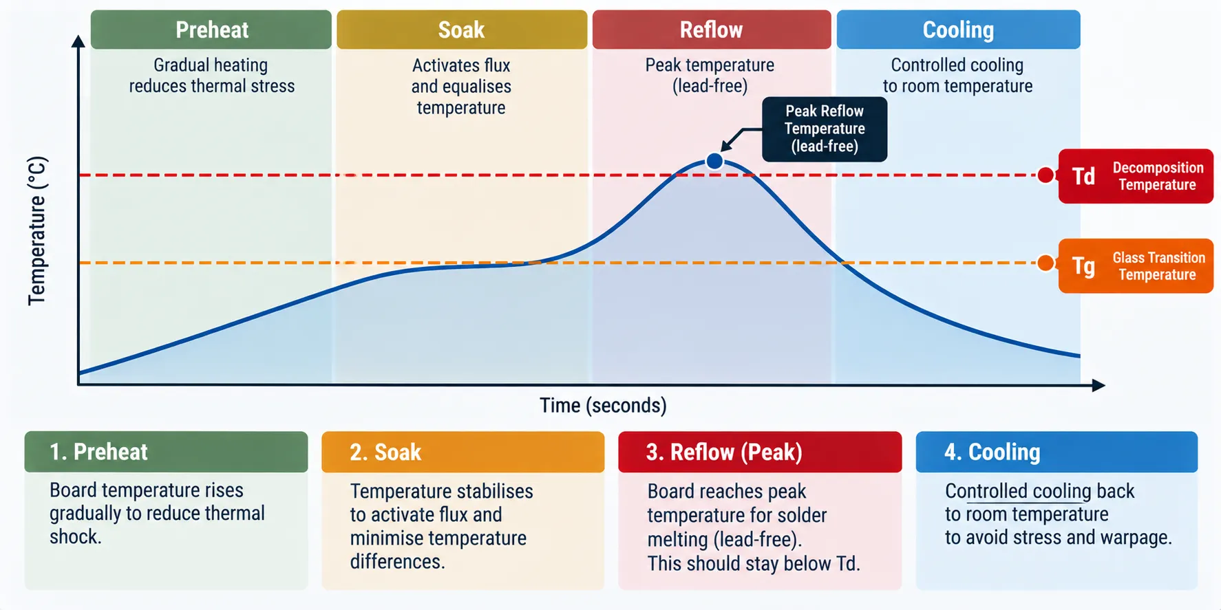
Only if its Td and Tg match the reflow profile, because lead-free solder needs higher temperatures than leaded solder. An Isola assessment from around 2003 puts lead-free peak reflow near 260 C and argues that Td matters at least as much as Tg.
That paper is old, and it comes from a single laminate supplier, so treat it as direction, not a spec. Check your laminate’s datasheet for its own Td and delamination data.
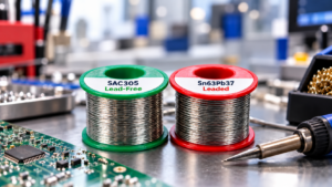
High temperature PCB materials, such as high-Tg FR4, polyimide and ceramic, give you more margin. We run boards through reflow, which is why we ask about Td before we quote. For the solder side, see our note on lead-free versus leaded solder.
Why do high frequency circuits need special PCB materials?
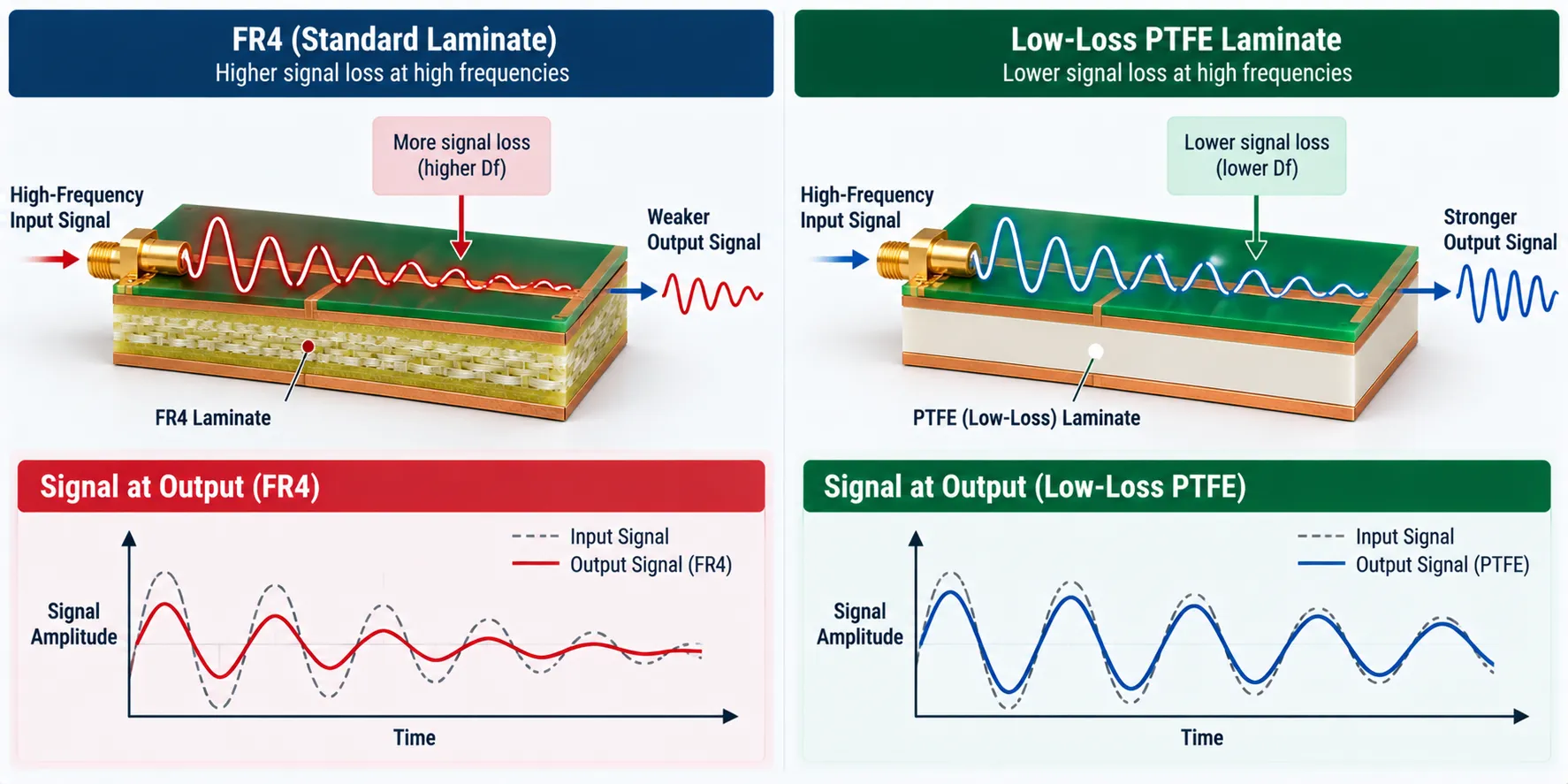
Standard FR4 loses signal integrity as frequency climbs, so RF, microwave and fast digital designs use PTFE-based or ceramic-filled laminates. These high frequency PCB materials have lower dielectric loss and steadier electrical properties across frequency and temperature.
Among the types of RF PCB material, Rogers is the name most designers know. RO3000 laminates are ceramic-filled PTFE composites aimed at commercial microwave and RF work.
Their Dk runs from 3.0 to 10.2 across the series, which is why 5G and radio designers pick by grade.
The RO4000 family is the easier one to build with. Rogers RO4350B lists a Dk of 3.48 with a tight tolerance and a typical Df of 0.0037, both at 10 GHz, and it processes much like FR4.
For a Rogers engineer’s view of the trade-offs, see this 2011 Microwave Journal post. Low-loss families from other makers, such as Panasonic’s MEGTRON line, serve the same need. The trade-off is cost, so keep them for designs that truly need them.
When do you need flexible PCB materials?
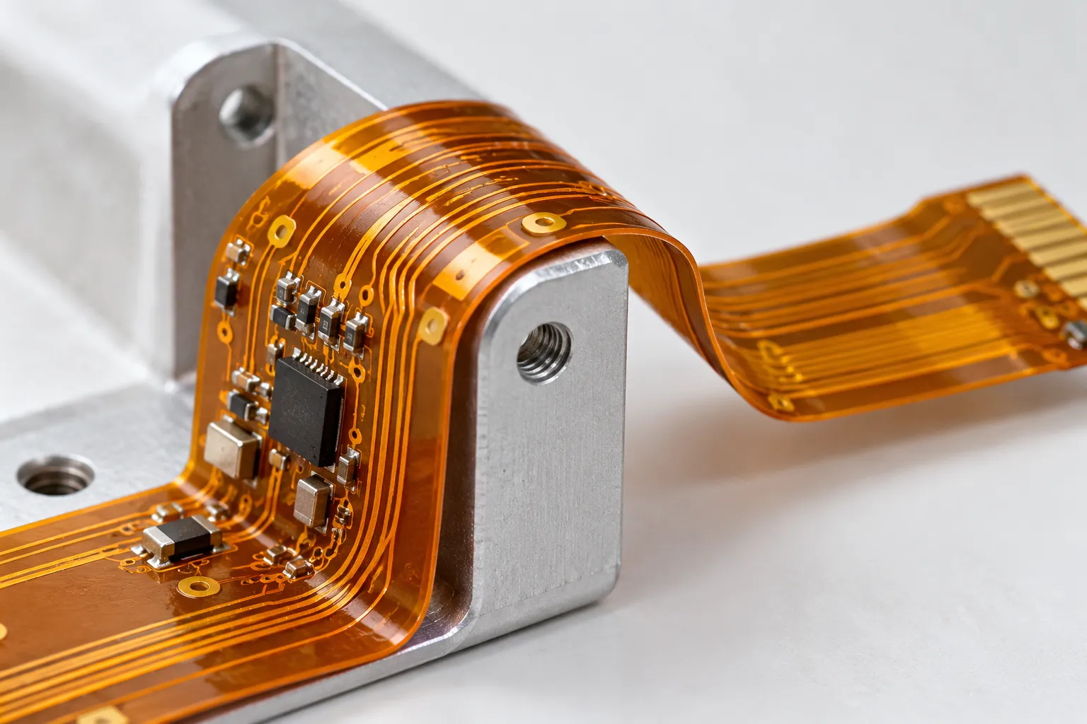
When the circuit must bend, fold or fit a space a rigid board cannot. Flexible PCB materials are usually polyimide, which survives repeated flexing without cracking.
Polyimide also handles heat well. Qnity’s Kapton FPC film page lists UL ratings of 240 C for electrical use and 200 C for mechanical use (page updated June 2026).
Flex and rigid-flex designs keep spreading in compact consumer products and wearables. Decide early, ideally with your assembly partner, because the choice changes how the board is built. We also cover rigid-flex PCBs separately.
Which PCB material fits which application?
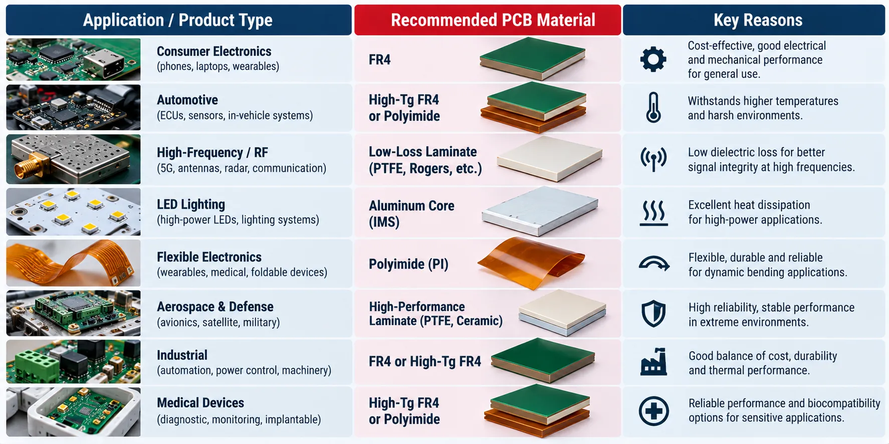
Match the material to the problem your product actually has, not to the most impressive datasheet. This table is our rule of thumb, not a standard.
| Your product | Main risk | Start with |
|---|---|---|
| Consumer gadget, controller | Cost | FR4 |
| Cheap single-layer board | Cost | FR-2, CEM-1 or CEM-3 |
| Automotive electronics | Heat, vibration, thermal cycling | High-Tg FR4, or metal core for lighting and power |
| Aerospace | Reliability across big temperature swings | Polyimide, ceramic or PTFE, by function |
| Medical devices | Reliability and small size | FR4, or polyimide flex and rigid-flex |
| Radar, RF, 5G telecommunications | Signal loss | PTFE or Rogers-type laminate |
| LED lighting, power electronics | Heat | Aluminum metal core |
| Wearable, folded assembly | Bending | Polyimide flex |
| High-power, high-reliability | Heat and stability | Ceramic |
Real products mix needs. A radio with a power stage may want two materials, and that is a design conversation, not a table lookup. See how we support automotive electronics and telecommunications builds.
How do IPC-4101 and UL 94 help you compare PCB materials?
They give you a shared language, so two laminates can be compared on the same terms. IPC-4101 is the specification for rigid laminate and prepreg base materials, and it sorts them into numbered “slash sheets” with required property ranges. UL 94 is the flammability rating, and V-0 is the grade most boards ask for.
IPC-4101 has been revised again. DIN Media lists Edition F, dated February 2026, so check which edition your drawing cites. Ask your supplier which slash sheet a laminate meets, instead of accepting a brand name alone.
What do PCB materials cost, and why are laminate prices rising in 2026?
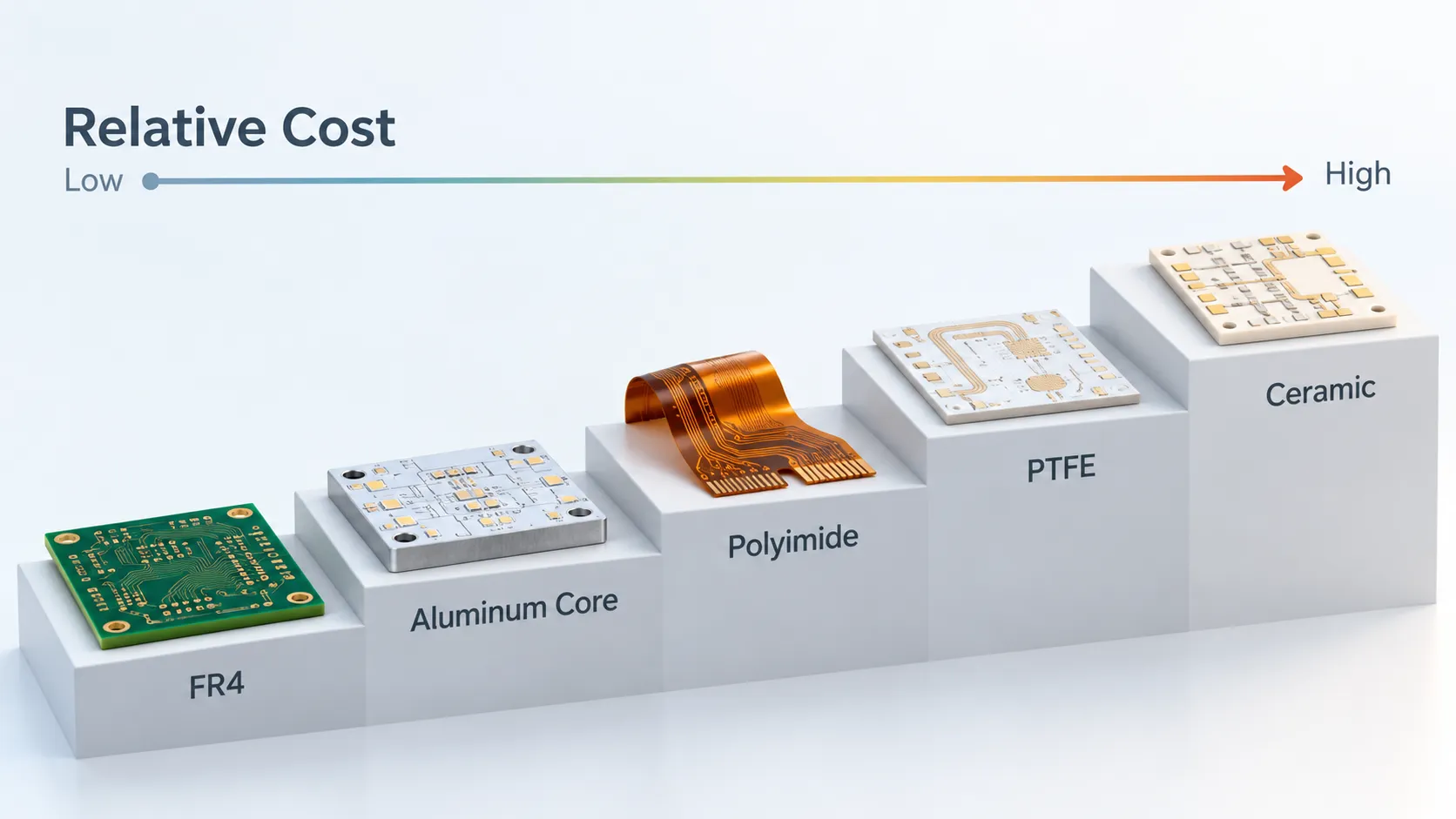
Laminate is a large part of bare board cost, and 2026 has been volatile. Resonac announced increases of about 30 percent on copper-clad laminates and prepregs, effective March 1, 2026, citing copper foil and glass cloth costs, labor and transport.
That is one supplier’s notice, so do not assume every laminate rose by the same amount. For a PCB material cost comparison, FR4 is cheapest, then specialty and high-Tg grades, then PTFE and ceramic, with metal core landing in between depending on design.
Fix your material early, ask for quote validity dates, and name approved alternates so a price jump does not stall your build.
How do you choose the right PCB material?
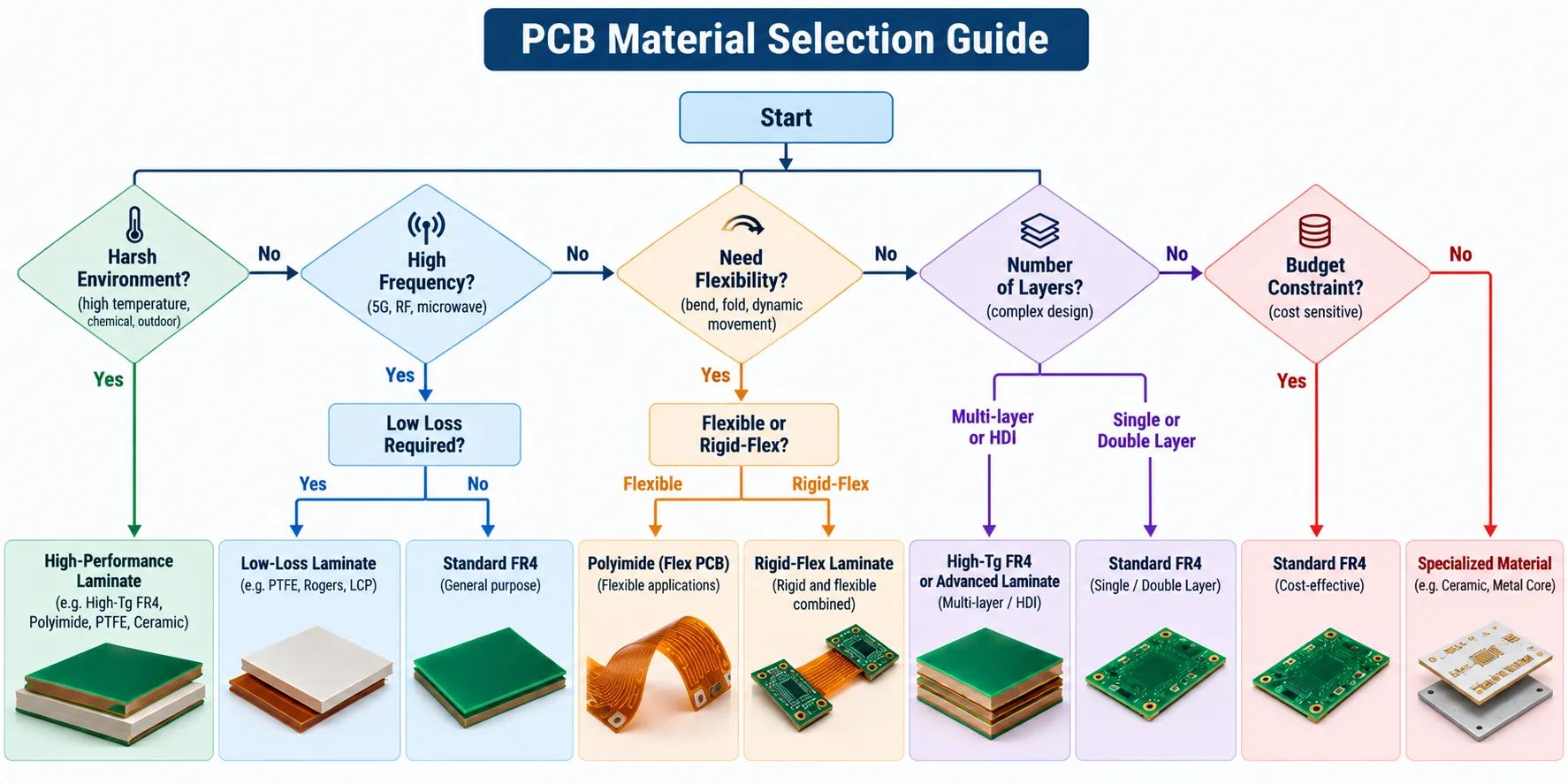
PCB material selection comes down to four questions, asked in order. Stop at the first one that rules FR4 out.
- Operating environment: high heat or power points to metal core or ceramic.
- Operating frequency: high-speed or RF designs may need high frequency materials.
- Flex or space limits: you may need flex or rigid-flex.
- Budget and volume: FR4 is the cost-effective choice for most standard boards.
Changing the substrate after layout is usually major rework, so decide early. If you want a second opinion on a design, talk to our team.
How do board thickness, copper weight and fabrication fit in?
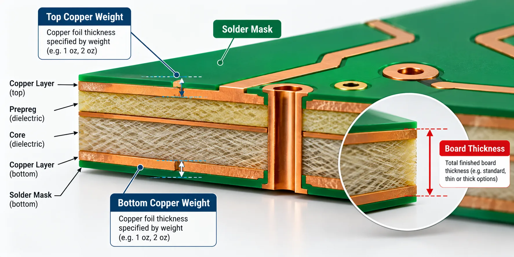
They should be chosen alongside the substrate, not after it. Standard boards typically run 0.8mm to 1.6mm. Thicker boards add rigidity, and thinner ones suit compact or flexible designs.
Copper weight is measured in ounces per square foot. Heavier copper carries more current but adds cost and can affect trace spacing. A high-power metal-core design often pairs with heavier copper.
Materials also behave differently through fabrication. Lamination, etching, drilling, copper plating and solder mask application all change with the laminate, and PTFE or ceramic need different handling than FR4. Raise that with your fabricator before layout is final.
What is the bottom line on PCB materials?
No single material fits every design, and FR4 is the reliable default. Knowing the alternatives keeps you from forcing a standard material into the wrong job.
If you are weighing options for a build, see our PCB assembly services and how our assembly process works.
Frequently asked questions
What is the most common PCB material?
FR4 is the most common PCB material. It is a glass-reinforced epoxy laminate, and it dominates because it balances cost, mechanical strength and electrical insulation. It suits most consumer and industrial boards. Specialty materials only enter when heat, frequency or bending needs go beyond what FR4 can handle.
When should I use flexible PCB material instead of rigid FR4?
Use flexible material, typically polyimide, when the design must bend, fold or fit a space a rigid board cannot. It also suits moving parts and compact products such as wearables. If the board never moves after assembly, rigid FR4 is usually cheaper and simpler to build.
Why do high-frequency circuits need special PCB materials?
Standard FR4 has more signal loss at high frequency, so RF and fast digital circuits use PTFE-based laminates to keep signals clean. Lower Df means less energy is lost as heat, and a steady Dk keeps signal timing predictable across frequency and temperature.
WHAT CHANGED: REWRITTEN
What is the difference between PCB substrate material and laminate material?
The substrate is the structural base layer of the board. Laminate materials are the resin systems that bond copper and substrate layers in multilayer boards. In casual use people mix the terms, and a copper-clad laminate is often sold as the substrate itself.
Is metal-core PCB material more expensive than FR4?
Yes. Metal core and ceramic cost more than FR4, but they pay off in high-power designs that need better heat dissipation, such as LED lighting and power stages. If heat is not a real problem for your product, you will usually be paying for performance you never use.
What is the difference between standard FR4 and high-Tg FR4?
High-Tg FR4 keeps its stiffness to a higher temperature than standard FR4 before the resin softens. That helps with lead-free assembly, thick boards and hot operating environments. It costs a little more, so use it when reflow or operating heat is a genuine concern, and check Td as well.
Can you mix different PCB materials in one board?
Yes, hybrid stack-ups exist, such as a high-frequency laminate layer combined with FR4 layers to control cost. They need careful design because different materials expand at different rates. Agree the stack-up with your fabricator and assembler before layout is finished.
FR4 vs polyimide PCB: which should I use?
Use FR4 unless the board has to bend. FR4 is rigid, cheaper and easy to source. Polyimide costs more but flexes repeatedly, handles higher heat and suits wearables and tight enclosures. If part of the board must flex and part must stay rigid, a rigid-flex design combines both materials in one assembly.
FR4 vs Rogers PCB material: when is Rogers worth it?
Rogers is worth it when signal loss decides whether the product works, typically RF, microwave, radar or 5G designs. FR4 is cheaper and fine for lower frequencies. Rogers laminates cost more, so many designers use them only on the layers that carry the high-frequency signal.