THE 30-SECOND VERSION
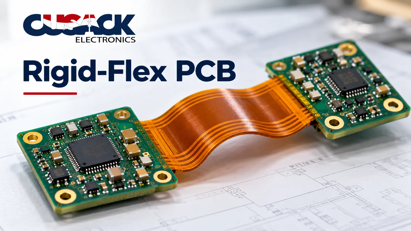
A rigid-flex PCB joins rigid board sections and flexible polyimide sections into one continuous circuit, removing the connectors and cables that would otherwise link them. It costs more per board and usually less per assembly. The number that decides whether yours survives is bend radius, and the published guidance on it varies by a factor of ten, so take that figure from your fabricator and the current standard rather than from an article.
A rigid-flex PCB is the only board type where the mechanical engineer and the electrical engineer have to agree before either can finish their job. That is the whole difficulty, and most of the cost.
Here is my flat opinion. Rigid-flex is oversold as a miniaturisation trick and undersold as a reliability one. The space saving is real but modest; the reliability gain from deleting a connector, a cable, and two crimp joints is the part that actually pays.
And one finding I did not expect when I went looking: the industry cannot agree on the most important number in flex design. More on that below, because it matters more than anything else here.
What Is a Rigid-Flex PCB?
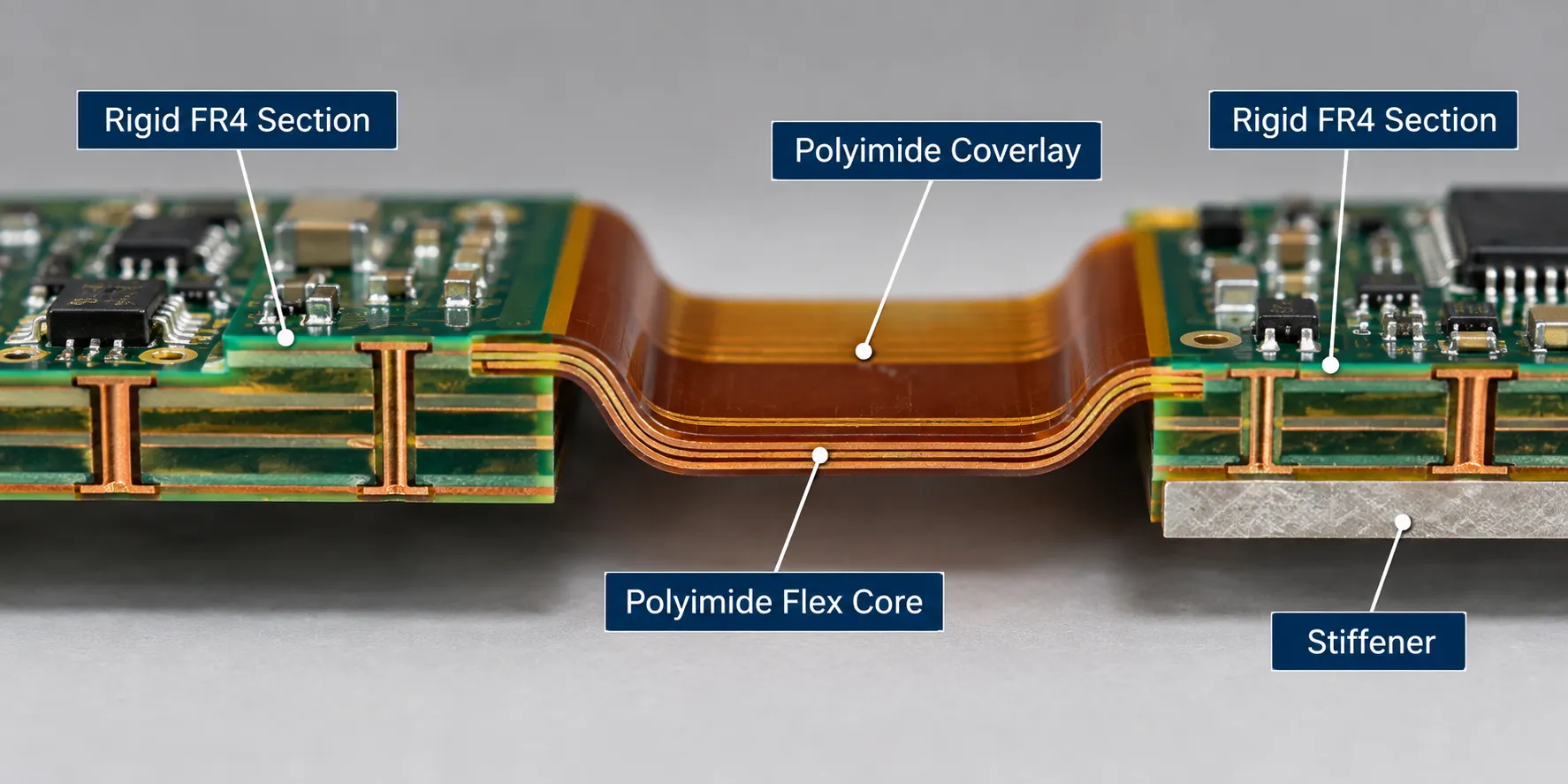
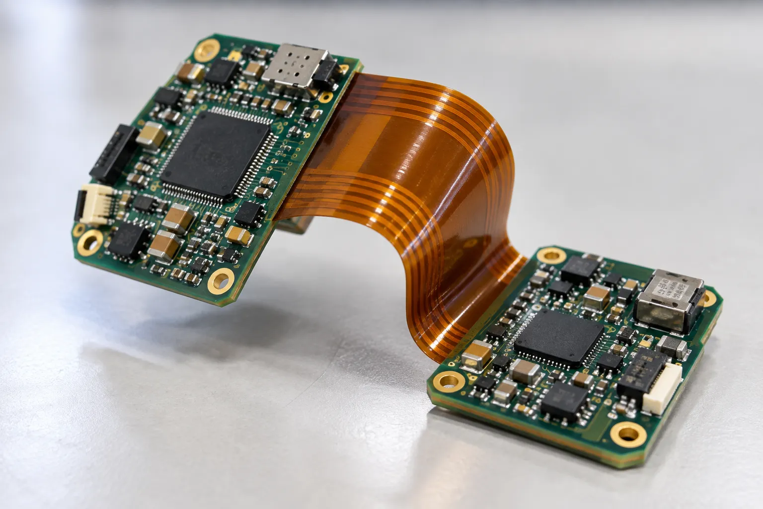
A rigid-flex PCB is a single circuit board built from both rigid and flexible layers, where the flexible layers run continuously through the rigid sections rather than being attached to them.
Picture a hardback book. The covers are stiff, the spine bends, and the pages run through both without a join. A rigid-flex board works the same way: the copper never stops at a connector, it simply passes from the stiff part into the bendable part.
That continuity is the point. Every connector you remove is a contact that cannot corrode, loosen, or be assembled wrong.
What Is It Made Of?
The flexible layers are polyimide, a film that tolerates bending and high temperature far better than the glass-reinforced epoxy used in rigid boards.
- Polyimide substrate: the flexible base film. Kapton is the long-standing brand name for it, and many engineers still say Kapton when they mean any polyimide film.
- Rolled annealed copper: the conductor of choice in flex areas, because its elongated grain structure survives repeated bending where standard electrodeposited foil cracks.
- Coverlay: a polyimide film laminated over the traces in place of liquid solder mask, which would crack when bent.
- Adhesiveless laminate: copper bonded directly to the polyimide with no adhesive layer, giving a thinner, more thermally stable flex circuit.
- Stiffener: a local backing of FR4, polyimide, or steel, added where a connector mounts or a part needs support.
The rigid sections are usually ordinary FR4, and the choice of substrate drives a lot of what follows. I have set out the broader options in my guide to PCB materials.
Rigid Flex vs Flex PCB: What Actually Differs?
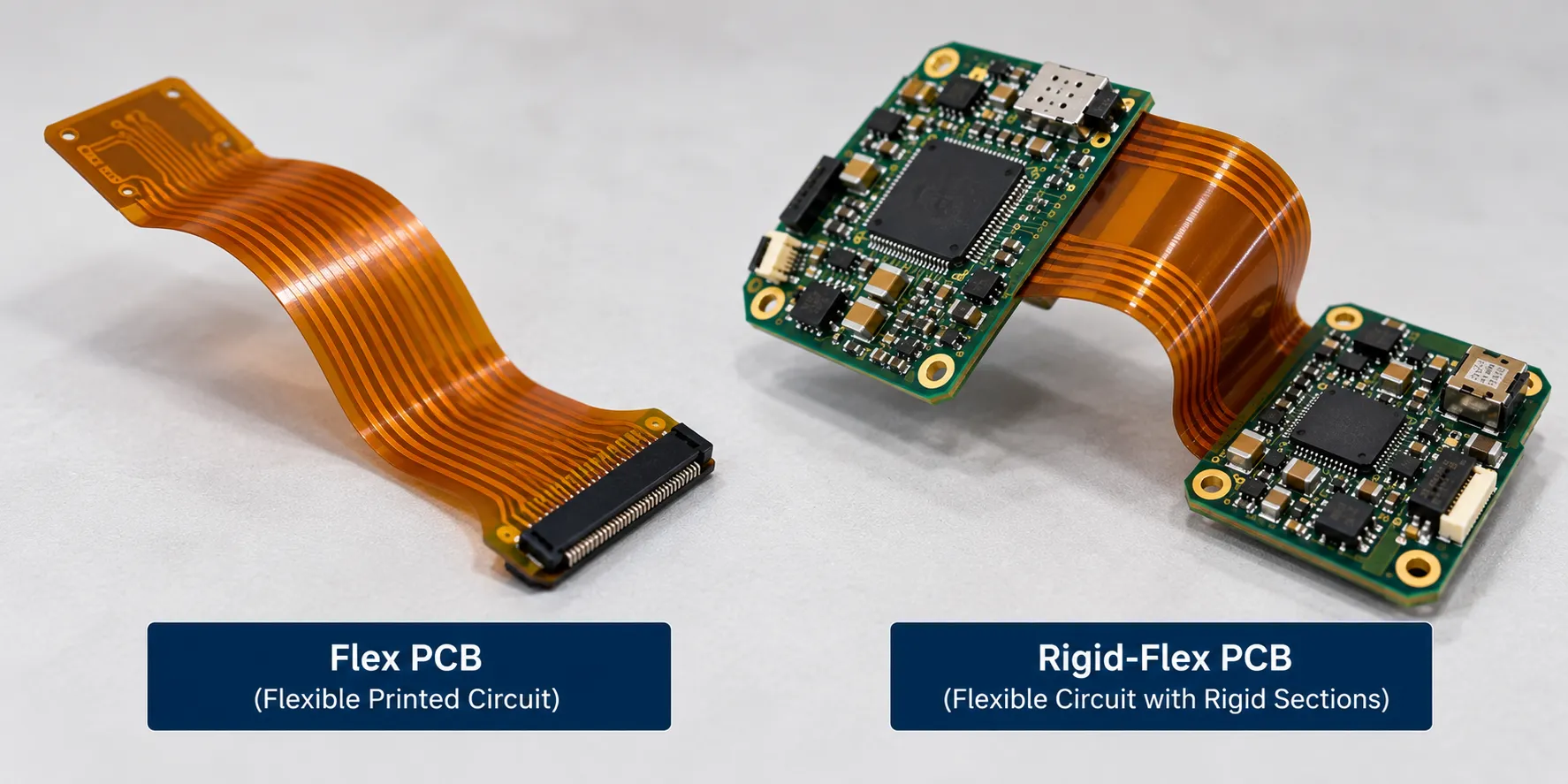
The difference between rigid-flex vs flex PCB is where the components sit. A plain flexible printed circuit is bendable throughout and usually terminates in a connector; a rigid-flex board has built-in rigid areas designed to carry parts.
| Rigid-flex PCB | Flex PCB | |
|---|---|---|
| Construction | Rigid and flexible layers in one board | Flexible layers only |
| Component mounting | On the rigid sections | Needs stiffeners added |
| Termination | Integrated, no connector needed | Usually a ZIF or soldered tail |
| Layer count | Commonly 4 to 12, sometimes more | Typically 1 to 4 |
| Fabrication cost | Highest | Moderate |
| Assembly handling | Rigid areas give support | Needs a carrier throughout |
Choose the flexible circuit when it is essentially a shaped cable carrying signals between two assemblies. Choose the hybrid when parts have to mount at both ends and you want the interconnect to disappear.
How Do You Read a Rigid Flex PCB Stackup?
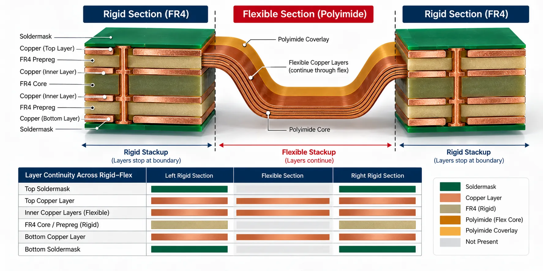
A rigid flex PCB stackup is described by how many layers are rigid and how many carry on into the flex. A four-layer board with two flex layers running through is a different animal from a four-layer board with one.
The rule that governs everything: only the layers you route into the flex section have to bend, and every layer you add there makes the flex thicker and the bend radius larger.
So a designer’s instinct to route everything everywhere is expensive here in a way it is not on a rigid board. Keep the flex layer count down and the mechanical constraints get easier.
Where density forces the layer count back up, microvias and sequential build-up are the usual escape, which puts you into HDI PCB territory on the rigid sections.
Symmetry matters too. An unbalanced flex stackup wants to curl, so the flexible layers are normally arranged symmetrically about their own centre, independently of how the rigid sections are built.
Where several flex layers must bend together through a tight radius, they are sometimes laminated unbonded in the bend area, so each layer can slide slightly rather than all of them stretching at different radii.
Bend Radius: The Number the Industry Disagrees On
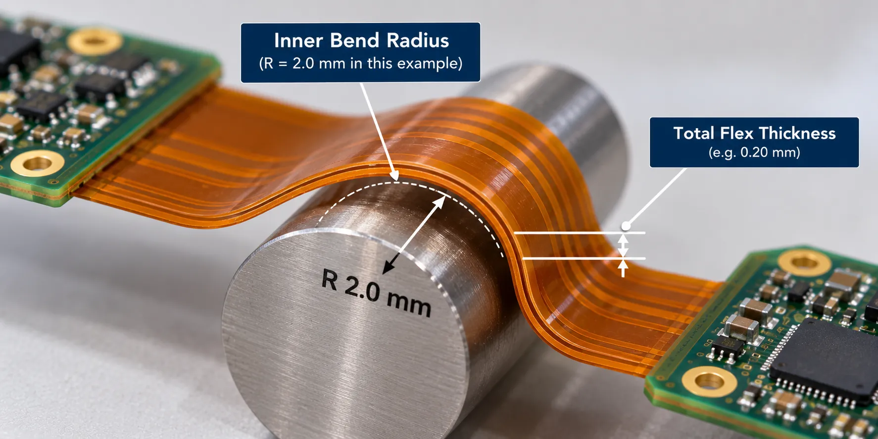
Bend radius is specified as a multiple of the total flex thickness, written as a number followed by T. A 10-mil flex at 10T needs a 100-mil inner radius.
Static bends, folded once at assembly and left alone, need far less than dynamic flex, where the circuit moves repeatedly in service. That much everyone agrees on.
The actual numbers are another matter, and I went looking expecting consistency.
| Source | Static bend | Dynamic flex |
|---|---|---|
| Altium Resources, updated April 2026 | 6T minimum, 10T recommended | 100T |
| FastTurn PCB, December 2025 | 10T | 20T |
| Siemens blog, October 2025 | Not separately stated | At least 10T |
Look at the dynamic column. Those three figures span a factor of ten, and they come from an EDA vendor, a fabricator, and a major software company, all published within the last eighteen months.
I am not going to adjudicate between them, because the honest answer is that it depends on layer count, copper type, and cycle count, and no single multiplier covers all three. What I will say is that a dynamic flex design sourced from a blog figure is a gamble.
Take the number from two places: the current standard, and the fabricator who will actually build it. IPC-2223F, the Sectional Design Standard for Flexible and Rigid-Flexible Printed Boards, was published in 2026 and supersedes IPC-2223E from 2020.
If a supplier quotes you IPC-2223 without a letter, ask which revision. IPC-2223 moved recently enough that the answer tells you how current their process documentation is.
Which Rigid Flex PCB Design Rules Prevent Failures?
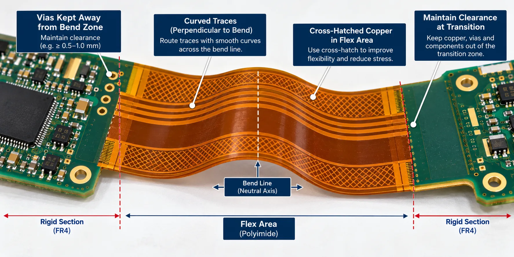
Most rigid flex PCB design failures happen in two places: inside the bend, and at the rigid-to-flex transition.
In the flex area:
- Run traces perpendicular to the bend line. A trace crossing the bend at an angle sees uneven strain along its length.
- Curve the corners. Sharp 90 degree turns concentrate stress exactly where the copper is already working hardest.
- Cross-hatch the copper planes. A solid plane in a bend area is a stiff sheet; a hatched one bends.
- Keep vias out entirely. A via in a bend zone is a crack waiting for a cycle count.
- Stagger traces on adjacent layers rather than stacking them directly above one another.
At the transition, where the rigid section ends and the flex begins:
- Hold vias and plated holes back from the boundary. That edge is a stress riser, and anything plated near it fails first.
- Step the transition rather than ending all rigid layers at the same line.
- Round the coverlay opening. A square corner in the coverlay tears from the corner.
That transition zone is important enough that the current performance specification added requirements for it. IPC-6013F, published in 2026 to supersede the 2021 E revision, lists new requirements for rigid-to-flex transition zones among its changes.
Get these settled at layout, because none of them is fixable later. That is the argument for a design for manufacturability review, and the groundwork sits in my guide to PCB layout design.
What Does Rigid Flex PCB Manufacturing Involve?
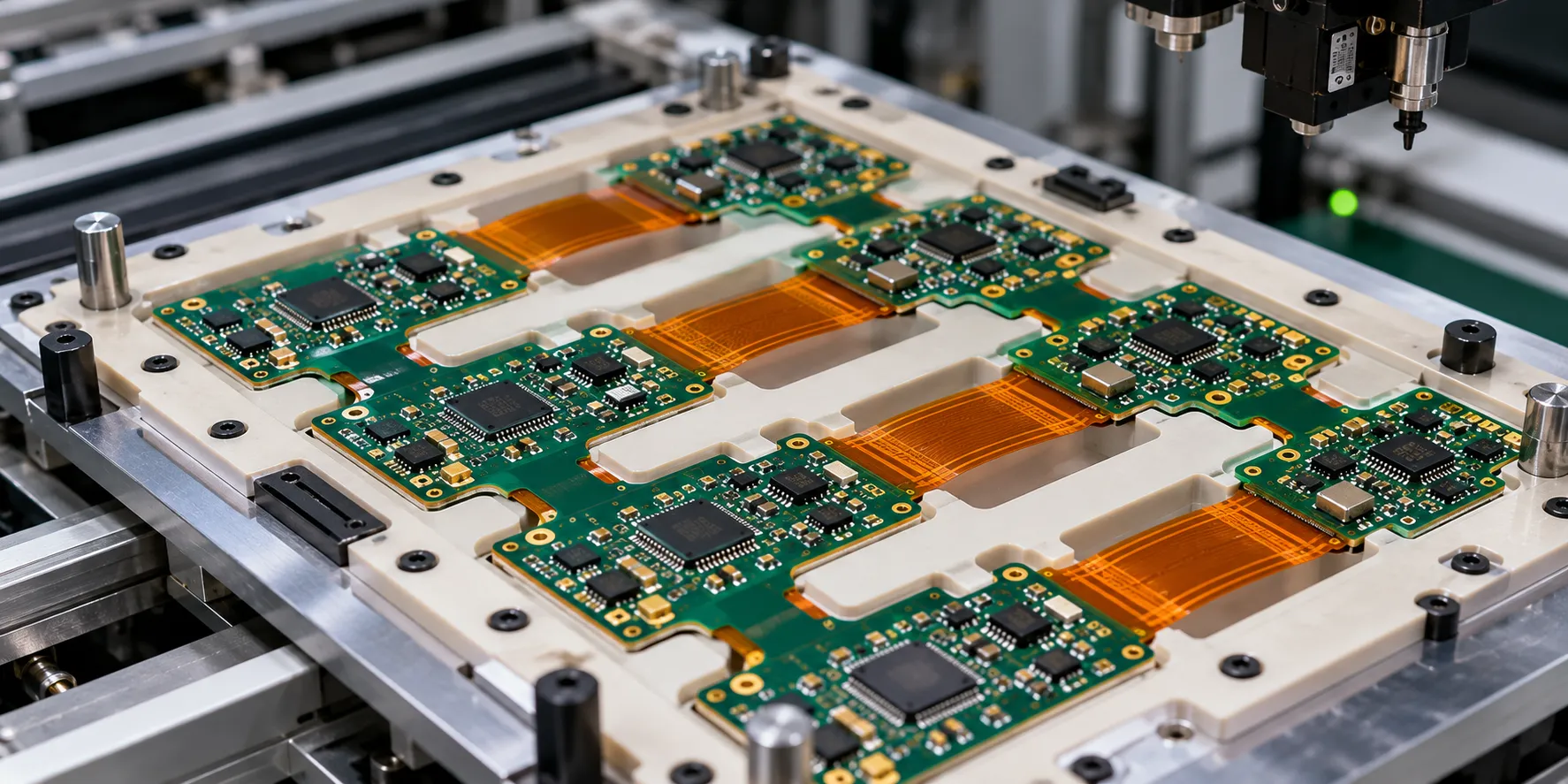
Rigid flex PCB manufacturing builds the flexible core first, then laminates the rigid sections around it, and finally removes the rigid material from the areas that need to bend.
That last step is the one that makes these boards expensive. Cutting the rigid layers away without nicking the polyimide underneath takes depth-controlled routing or laser depanelling, and a cut that goes a few microns too deep has scrapped the panel after every prior process step has been paid for.
Flex PCB assembly brings its own handling problem. A board that bends will not sit flat on a conveyor, so the panel runs in a machined carrier fixture that supports the flex areas through printing, placement and reflow.
That fixture is real tooling with a real cost and lead time, and it is the item most often missing from a first quote. Ask about it explicitly.
The soldering itself is ordinary surface-mount work on the rigid sections, following the same sequence as any other board, which I have walked through in my guide to the SMT assembly process.
Polyimide absorbs moisture more readily than FR4, so these panels are usually baked before reflow. Skip that and the trapped moisture delaminates the flex layers at peak temperature.
What Does Rigid-Flex Cost, and When Is It Worth It?
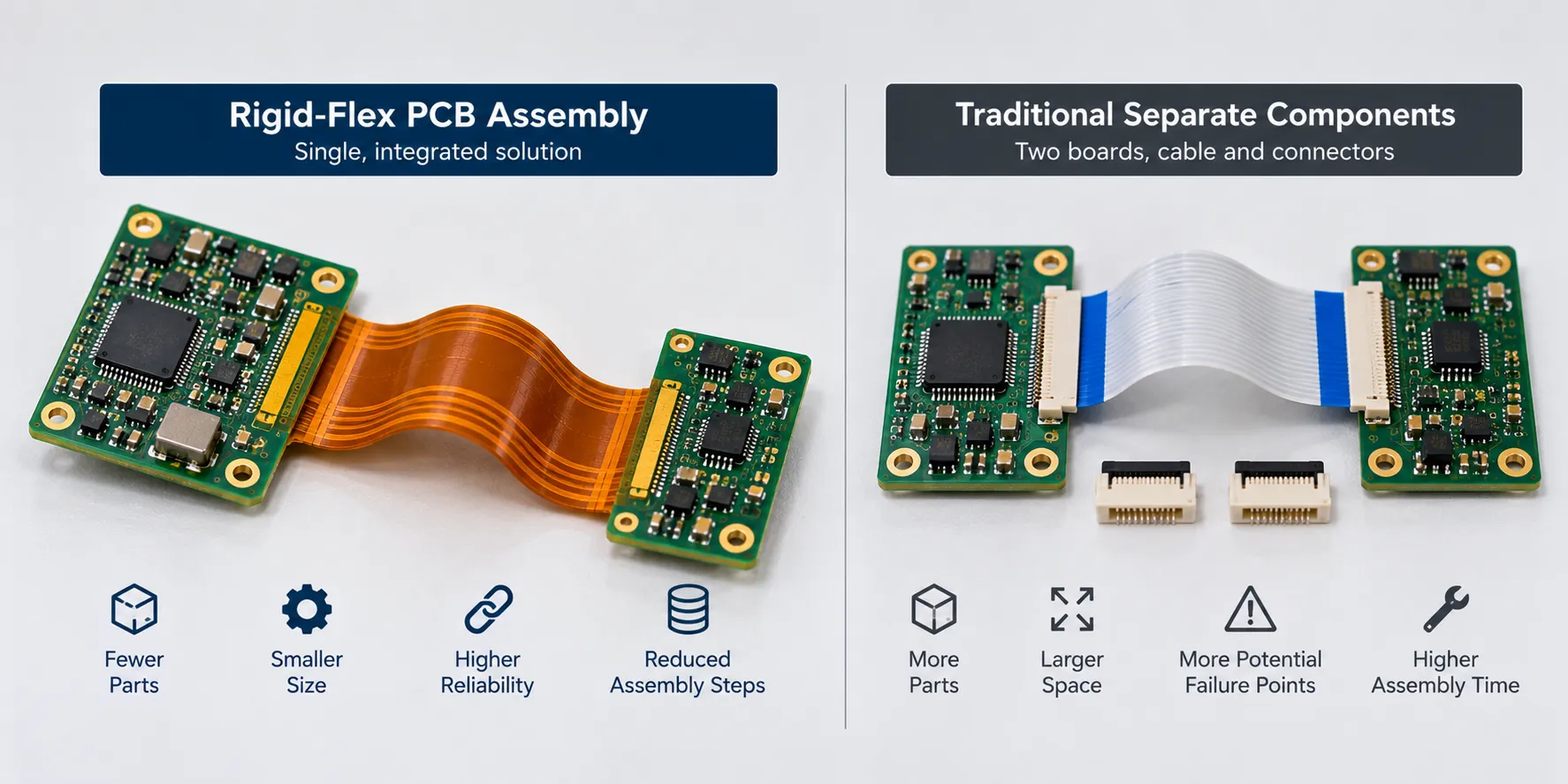
Rigid flex cost is higher per board than rigid and often lower per finished assembly, which is why comparing bare board quotes tells you almost nothing.
The honest comparison counts everything the construction deletes: two connectors, a cable, the labour to fit them, the test step that checks they are seated, and the field failures when one is not.
- What raises the price: sequential lamination, depth-controlled routing, lower panel utilisation, carrier fixtures, and tighter inspection.
- What lowers the total: fewer parts to buy, fewer assembly operations, fewer test points, less rework.
- What to do about it: keep the flex area small, keep flex layer count low, and avoid dynamic flex unless the product genuinely moves.
Where Are Rigid Flex PCB Applications Found?
Rigid flex PCB applications cluster where space is tight, weight matters, or a connector failure is unacceptable.
- Aerospace and defence: vibration destroys connectors, and in aerospace weight is costed per gram.
- Medical devices: implantables and endoscopes need circuits that fold into shapes a rigid board cannot reach. Medical devices also tend to demand the higher IPC class.
- Wearables and compact consumer products: the board folds around a battery or into a hinge.
- Industrial sensors: a sealed assembly with no internal connectors has fewer ways to fail.
Notice how many of those are reliability cases rather than space cases. That is the pattern I keep seeing.
How Do You Choose a Rigid Flex PCB Manufacturer?
Ask capability questions, not price questions, at least first.
Ask what layer counts and flex layer counts they hold routinely, what their depth-control tolerance is on the rigid cutout, whether they build to IPC-6013 Class 2 or Class 3, and which revision of IPC-6013 their inspection criteria follow, and whether carrier fixtures are quoted separately.
My caveat, and it is a real one: a shop that quotes rigid-flex noticeably cheaper than everyone else is usually running closer to its process limits, not working more efficiently. Yield on these boards is where the money actually goes.
Frequently Asked Questions
What is the minimum bend radius for a rigid-flex PCB?
It depends on total flex thickness, layer count, copper type, and whether the bend is static or dynamic. Published guidance ranges widely, particularly for dynamic flex. Take the figure from IPC-2223F and from the fabricator building your board, and treat any single multiplier quoted without those caveats as a starting point rather than a specification.
Can components be mounted on the flexible section?
Generally no, and you should design so the question does not arise. Parts belong on the rigid sections. Where something genuinely must sit on flex, it needs a stiffener underneath to create a local rigid area, which adds cost and a lamination step.
Why is rolled annealed copper used instead of standard foil?
Grain structure. Rolled annealed copper has elongated grains running along the sheet, which tolerates repeated bending far better than the columnar grains in electrodeposited foil. For a static single fold the difference may not matter; for dynamic flex it decides the cycle life.
Does a rigid-flex board need to be baked before assembly?
Usually yes. Polyimide takes up moisture from the air more readily than FR4, and moisture trapped in the flex layers turns to steam at reflow temperature and delaminates them. Your assembler should bake as a matter of routine, but confirm it rather than assume.
Is rigid-flex worth it for a low-volume product?
Sometimes, but for a different reason than at high volume. At low volume the per-board premium is painful and the assembly labour saving is small. The case holds when reliability or physical shape genuinely rules out boards and cables, not when the motivation is tidiness.